How does a pitot tube work?
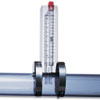
Pitot tubes were invented by Henri Pitot in 1732 to measure the flowing liquid or air velocity. Basically a differential pressure (d/p) flowmeter, a pitot tube measures two pressures: the static and the total impact pressure. The static pressure is the operating pressure in the pipe, duct, or the environment, upstream to the pitot tube. It is measured at right angles to the flow direction, preferably in a low turbulence location (Figure 2-9).
The total impact pressure (P
T) is the sum of the static and kinetic pressures and is detected as the flowing stream impacts on the pitot opening. To measure impact pressure, most pitot tubes use a small, sometimes L-shaped tube, with the opening directly facing the oncoming flowstream. The point velocity of approach (V
P) can be calculated by taking the square root of the difference between the total pressure (P
T) and the static pressure (P) and multiplying that by the C/D ratio, where C is a dimensional constant and D is density:
Vp = C(PT - P)½/D
When the flowrate is obtained by multiplying the point velocity (V
P) by the cross-sectional area of the pipe or duct, it is critical that the velocity measurement be made at an insertion depth which corresponds to the average velocity. As the flow velocity rises, the velocity profile in the pipe changes from elongated (laminar) to more flat (turbulent). This changes the point of average velocity and requires an adjustment of the insertion depth. Pitot tubes are recommended only for highly turbulent flows (Reynolds Numbers > 20,000) and, under these conditions, the velocity profile tends to be flat enough so that the insertion depth is not critical.
In 1797, G.B. Venturi developed a short tube with a throat-like passage that increases flow velocity and reduces the permanent pressure drop. Special pitot designs are available that, instead of providing just an impact hole for opening, add a single or double venturi to the impact opening of the pitot tube. The venturi version generates a higher differential pressure than does a regular pitot tube.

Static Pressure Measurement

In jacketed (dual-walled) pitot-tube designs, the impact pressure port faces forward into the flow, while pitot static tube port do not, but are, instead, spaced around the outer tube. Both pressure signals (P
T and P) are routed by tubing to a d/p indicator or transmitter. In industrial applications, the static pressure (P) can be measured in three ways: 1) through taps in the pipe wall; 2) by static pitot probes inserted in the process stream; or 3) by small openings located on the pitot tube itself or on a separate aerodynamic element.
Wall taps can measure static pressures at flow velocities up to 200 ft/sec. A pitot static tube (resembling an L-shaped pitot tube) can have four holes of 0.04 inches in diameter, spaced 90° apart. Aerodynamic bodies can be cylinders or wedges, with two or more sensing ports.
Errors in detecting static pressure arise from fluid viscosity, velocity, and fluid compressibility. The key to accurate static pressure detection is to minimize the kinetic component in the pressure measurement.
Single-Port Pitot Tubes
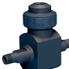
A single-port pitot tube can measure the flow velocity at only a single point in the cross-section of a flowing stream (Figure 2-10). The probe must be inserted to a point in the flowing stream where the flow velocity is the average of the veloc

ities across the cross-section, and its impact port must face directly into the fluid flow. The pitot tube can be made less sensitive to flow direction if the impact port has an internal bevel of about 15°, extending about 1.5 diameters into the tube.
If the pressure differential generated by the venturi is too low for accurate detection, the conventional pitot tube can be replaced by a pitot venturi or a double venturi sensor. This will produce a higher pressure differential.
A calibrated, clean and properly inserted single-port pitot tube can provide ±1% of full scale flow accuracy over a flow range of 3:1; and, with some loss of accuracy, it can even measure over a range of 4:1. Its advantages are low cost, no moving parts, simplicity, and the fact that it causes very little pressure loss in the flowing stream. Its main limitations include the errors resulting from velocity profile changes or from plugging of the pressure ports. Pitot tubes are generally used for flow measurements of secondary importance, where cost is a major concern, and/or when the pipe or duct diameter is large (up to 72 inches or more).
Specially designed pitot probes have been developed for use with pulsating flows. One design uses a pitot probe filled with silicone oil to transmit the process pressures to the d/p cell. At high frequency pulsating applications, the oil serves as a pulsation dampening and pressure-averaging medium.
Pitot tubes also can be used in square, rectangular or circular air ducts. Typically, the pitot tube fits through a 5/16-in diameter hole in the duct. Mounting can be by a flange or gland. The tube is usually provided with an external indicator, so that its impact port can be accurately rotated to face directly into the flow. In addition, the tube can be designed for detecting the full velocity profile by making rapid and consistent traverses across the duct.
In some applications, such as EPA-mandated stack particulate sampling, it is necessary to traverse a pitot sampler across a stack or duct. In these applications, at each point noted in Figure 2-11, a temperature and flow measurement is made in addition to taking a gas sample, which data are then combined and taken to a laboratory for analysis. In such applications, a single probe contains a pitot tube, a thermocouple, and a sampling nozzle.
A pitot tube also can be used to measure water velocity in open channels, at drops, chutes, or over fall crests. At the low flow velocities typical of laminar conditions, pitot tubes are not recommended because it is difficult to find the insertion depth corresponding to the average velocity and because the pitot element produces such a small pressure differential. The use of a pitot venturi does improve on this situation by increasing the pressure differential, but cannot help the problem caused by the elongated velocity profile.
Averaging Pitot Tubes
Averaging pitot tubes been introduced to overcome the problem of finding the average velocity point. An averaging pitot tube is provided with multiple impact and static pressure ports and is designed to extend across the entire diameter of the pipe. The pressures detected by all the impact (and separately by all the static) pressure ports are combined and the square root of their difference is measured as an indication of the average flow in the pipe (Figure 2-12). The port closer to the outlet of the combined signal has a slightly greater influence, than the port that is farthest away, but, for secondary applications where pitot tubes are commonly used, this error is acceptable.
The number of impact ports, the distance between ports, and the diameter of the averaging pitot tube all can be modified to match the needs of a particular application. Sensing ports in averaging pitot tubes are often too large to allow the tube to behave as a true averaging chamber. This is because the oversized

port openings are optimized not for averaging, but to prevent plugging. In some installations, purging with an inert gas is used to keep the ports clean, allowing the sensor to use smaller ports.
Averaging pitot tubes offer the same advantages and disadvantages as do single-port tubes. They are slightly more expensive and a little more accurate, especially if the flow is not fully formed. Some averaging pitot sensors can be inserted through the same opening (or hot tap) which accommodates a single-port tube.
Area Averaging
Area-averaging pitot stations are used to measure the large flows of low pressure air in boilers, dryers, or HVAC systems. These units are available for the various standard sizes of circular or rectangular ducts (Figure 2-13) and for pipes. They are so designed that each segment of the cross-section is provided with both an impact and a static pressure port. Each set of ports is connected to its own manifold, which combines the average static and average impact pressure signals. If plugging is likely, the manifolds can be purged to keep the ports clean.
Because area-averaging pitot stations generate very small pressure differentials, it may be necessary to use low differential d/p cells with spans as low as 0-0.01 in water column. To improve accuracy, a hexagonal cell-type flow straightener and a flow nozzle can be installed upstream of the area-averaging pitot flow sensor. The flow straightener removes local turbulence, while the nozzle amplifies the differential pressure produced by the sensor.
Installation
Pitot tubes can be used as permanently installed flow sensors or as portable monitoring devices providing periodic data. Permanently installed carbon steel or stainless steel units can operate at up to 1400 PSIG pressures and are inserted into the pipe through flanged or screw connections. Their installation usually occurs prior to plant start-up, but they can be hot-tapped into an operating process.
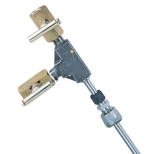
In a hot-tap installation (Figure 2-14), one first welds a fitting to the pipe. Then a drill-through valve is attached to the fitting and a hole is drilled through the pipe. Then, after partially withdrawing the drill, the valve is closed, the drill is removed and the pitot tube is inserted. Finally, the valve is opened and the pitot tube is fully inserted.
The velocity profile of the flowing stream inside the pipe is affected by the Reynolds number of the flowing fluid, pipe surface roughness, and by upstream disturbances, such as valves, elbows, and other fittings. Pitot tubes should be used only if the minimum Reynolds number exceeds 20,000 and if either a straight run of about 25 diameters can be provided upstream to the pitot tube or if straightening vanes can be installed.
Vibration Damage
Natural frequency resonant vibrations can cause pitot tube failure.

Natural frequency vibration is caused by forces created as vortices are shed by the pitot tube. The pitot tube is expected to experience such vibration if the process fluid velocity (in feet per second) is between a lower limit (VL) and an upper limit (V
H). The values of V
L and V
H can be calculated (for the products of a given manufacturer) using the equations below.
VL = 5253(M x Pr x D)/L
VH = 7879(M x Pr x D)/L
Where M = mounting factor (3.52 for single mount); Pr = probe factor (0.185 for 3/8-in diameter probes; 0.269 for 1/2-in; 0.372 for 3/4-in; and 0.552 for 1-in); D = probe diameter (inches); L = unsupported probe length in inches, which is calculated as the sum of the pipe I.D. plus the pipe wall thickness plus: 1.25 in for 3/8-in diameter probes; 1.5 in for 1/2-in; 1.56 in for 3/4-in; and 1.94 in for 1-in diameter probes.
Once the velocity limits have been calculated, make sure that they do not fall within the range of operating velocities. If they do, change the probe diameter, or its mounting, or do both, until there is no overlap.
 CLOSE
CLOSE