Apparent Strain
Stability Considerations
Transducer Designs
Installation Diagnostics
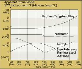
Figure 2-12: Apparent Strain Variation
with Temperature
Apparent strain is any change in gage resistance that is not caused by the strain on the force element. Apparent strain is the result of the interaction of the thermal coefficient of the strain gage and the difference in expansion between the gage and the test specimen. The variation in the apparent strain of various strain-gage materials as a function of operating temperature is shown in Figure 2-12. In addition to the temperature effects, apparent strain also can change because of aging and instability of the metal and the bonding agent.
Compensation for apparent strain is necessary if the temperature varies while the strain is being measured. In most applications, the amount of error depends on the alloy used, the accuracy required, and the amount of the temperature variation. If the operating temperature of the gage and the apparent strain characteristics are known, compensation is possible.
It is desirable that the strain-gage measurement system be stable and not drift with time. In calibrated instruments, the passage of time always causes some drift and loss of calibration. The stability of bonded strain-gage transducers is inferior to that of diffused strain-gage elements. Hysteresis and creeping caused by imperfect bonding is one of the fundamental causes of instability, particularly in high operating temperature environments.
Before mounting strain-gage elements, it should be established that the stressed force detector itself is uniform and homogeneous, because any surface deformities will result in instability errors. In order to remove any residual stresses in the force detectors, they should be carefully annealed, hardened, and stress-relieved using temperature aging. A transducer that uses force-detector springs, diaphragms, or bellows should also be provided with mechanical isolation. This will protect the sensor element from external stresses caused either by the strain of mounting or by the attaching of electric conduits to the transducer.
If stable sensors are used, such as deposited thin-film element types, and if the force-detector structure is well designed, balancing and compensation resistors will be sufficient for periodic recalibration of the unit. The most stable sensors are made from platinum or other low-temperature coefficient materials. It is also important that the transducer be operated within its design limits. Otherwise, permanent calibration shifts can result. Exposing the transducer to temperatures outside its operating limits can also degrade performance. Similarly, the transducer should be protected from vibration, acceleration, and shock.
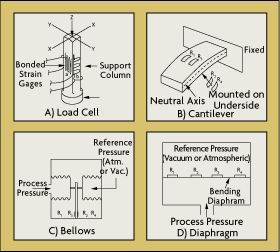
Figure 2-13: Strain Gage Installation Alternatives
Strain gages are used to measure displacement, force, load, pressure, torque or weight. Modern strain-gage transducers usually employ a grid of four strain elements electrically connected to form a Wheatstone bridge measuring circuit.
The strain-gage sensor is one of the most widely used means of load, weight, and force detection. In Figure 2-13A, a vertical beam is subjected to a force acting on the vertical axis. As the force is applied, the support column experiences elastic deformation and changes the electrical resistance of each strain gage. By the use of a Wheatstone bridge, the value of the load can be measured. Load cells are popular weighing elements for tanks and silos and have proven accurate in many other weighing applications.
Strain gages may be bonded to cantilever springs to measure the force of bending (Figure 2-13B). The strain gages mounted on the top of the beam experience tension, while the strain gages on the bottom experience compression. The transducers are wired in a Wheatstone circuit and are used to determine the amount of force applied to the beam.
Strain-gage elements also are used widely in the design of industrial pressure transmitters. Figure 2-13C shows a bellows type pressure sensor in which the reference pressure is sealed inside the bellows on the right, while the other bellows is exposed to the process pressure. When there is a difference between the two pressures, the strain detector elements bonded to the cantilever beam measure the resulting compressive or tensile forces.
A diaphragm-type pressure transducer is created when four strain gages are attached to a diaphragm (Figure 2-13D). When the process pressure is applied to the diaphragm, the two central gage elements are subjected to tension, while the two gages at the edges are subjected to compression. The corresponding changes in resistance are a measure of the process pressure. When all of the strain gages are subjected to the same temperature, such as in this design, errors due to operating temperature variations are reduced.
All strain gage installations should be checked using the following steps:
1. Measure the base resistance of the unstrained strain gage after it is mounted, but before wiring is connected.
2. Check for surface contamination by measuring the isolation resistance between the gage grid and the stressed force detector specimen using an ohmmeter, if the specimen is conductive. This should be done before connecting the lead wires to the instrumentation. If the isolation resistance is under 500 megaohms, contamination is likely.
3. Check for extraneous induced voltages in the circuit by reading the voltage when the power supply to the bridge is disconnected. Bridge output voltage readings for each strain-gage channel should be nearly zero.
4. Connect the excitation power supply to the bridge and ensure both the correct voltage level and its stability.
5. Check the strain gage bond by applying pressure to the gage. The reading should be unaffected.
| References & Further Reading | |
| Omegadyne Pressure, Force, Load, Torque Databook, OMEGADYNE, Inc., 1996 | |
| The Pressure, Strain, and Force Handbook, Omega Press LLC, 1996. | |
| Instrument Engineers' Handbook, Bela Liptak, CRC Press LLC, 1995. | |
| Marks' Standard Handbook for Mechanical Engineers, 10th Edition, Eugene A. Avallone, and Theodore Baumeister, McGraw-Hill, 1996. | |
| McGraw-Hill Concise Encyclopedia of Science and Technology, McGraw-Hill, 1998. | |
| Process/Industrial Instruments and Controls Handbook, 4th Edition, Douglas M. Considine, McGraw-Hill, 1993. | |
| Van Nostrand's Scientific Encyclopedia, Douglas M. Considine and Glenn D. Considine, Van Nostrand, 1997. |