Cookies on the OMEGA websites
We use cookies on this website, these cookies are essential for the website to work correctly.If you continue without changing your settings, we'll assume that you are happy to receive all cookies on this website.To find out more information about these cookies please click here.
CLOSE
Basket  |  Contact  |  Help  | 
Free Phone 0800 488 488
International+44(0) 161 777 6611
Layer N Banner

8-Channel Voltage Input USB Data Acquisition system

OM-USB-1208FS-1408FS

8-Channel Voltage USB Data Acquisition system | OM-USB-1208FS-1408FS

8-Channel Voltage USB Data Acquisition system

CE
  • Low Cost, Multifunction USB Devices with 4 Differential or 8 Single-Ended Analog Inputs
  • Provides 12-Bit (OM-USB-1208FS) or 14-Bit (OM-USB-1408FS) Analog Input Resolution
  • Maximum Sampling Rates Ranging from 1.2 kS/s to 50 kS/s
  • 2 Analog Outputs
  • 16 Digital I/O Lines
  • One 32-Bit Counter Input Channel
  • No External Power Required
USB, RS232, RS485 and Ethernet Data Acquisition Systems - View related products

Description

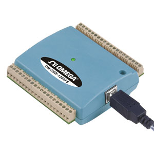
The OM-USB-1208FS and OM-USB-1408FS data acquisition modules offer four differential (DIFF) or eight single-ended (SE) analog inputs, two analog outputs, 16 digital I/O channels, and one counter input. These modules are USB 2.0 full speed voltage input data acquisition modules (fully compatible with both USB 1.1 and USB 2.0 ports). These are plug-and-play modules which draw power from the USB cable - no external power supply is required. All configurable options (including individual channel ranges) are software programmable, and the modules are fully software calibrated.

Both modules feature eight analog voltage input channels that are processed through a single A/D converter. The analog inputs to the OM-USB-1208FS are software configurable for either eight 11-bit single-ended or four 12-bit differential inputs. The analog inputs to the OM-USB-1408FS are software configurable for either eight 13-bit single-ended or four 14-bit differential inputs.

These modules have one 32-bit counter channel. The digital I/O channels are software programmable for input or output. Both models have two 12-bit analog outputs. The packaging for the OM-USB-1208FS and OM-USB-1408FS ensures ease of use in a variety of applications

The OM-USB-1208FS and OM-USB-1408FS data acquisition modules are supplied with TracerDAQ software which is a collection of four virtual instrument applications used to graphically display and store input data and generate output signals:

    • Strip Chart—Log and graph values acquire from analog inputs, digital inputs, temperature inputs and counter inputs
    • Oscilloscope—Display values acquired from analog inputs
    • Function Generator—Generate waveforms for analog outputs
    • Rate Generator—Generate waveforms for counter outputs

TracerDAQ PRO is an enhanced version of TracerDAQ. A comparison of some of the features included in TracerDAQ vs TracerDAQ PRO is shown on the PDF.

SOFTWARE
OM-USB-1208FS and OM-USB-1408FS modules ship with an impressive array of software, including the new TracerDAQ®, a full-featured, out-of-the-box data logging, viewing, and analysis application. Driver support and detailed example programs are included for Universal Library programming libraries for Microsoft® Visual Studio® programming languages, and other languages, including DASYLab®, and ULx for NI LabVIEW® (comprehensive library of Vls and example programs compatible with 32-bit and 64-bit LabVIEW v8.5 through 2013) and InstaCal™ installation, calibration and test utility - powerful solutions for programmers and non-programmers alike. These modules operate under Microsoft Windows® XP (32-bit only) and VISTA/7/8 (32-bit and 64-bit) operating systems.

ANALOG INPUT
OM-USB 1208FS: These devices provide eight, 11-bit single-ended analog inputs or four, 12-bit differential analog inputs.
OM-USB 1408FS: These devices provide eight, 13-bit single-ended analog inputs or four, 14-bit differential analog inputs. All devices support software selectable ranges that provide inputs from ±1V to ±20V in a differential configuration, and ±10V in a single-ended configuration.

GENERAL INFORMATION
SAMPLING RATE: When scanning continuously to computer memory (hardware-paced mode), the OM-USB-1208FS can sample at a maximum of 50 kS/s, and the OM-USB-1408FS can sample at a maximum of 48 kS/s.

CHANNEL-GAIN QUEUE
The channel-gain queue feature lets you configure a list of channels and gains for each scan. Each channel can have a different gain setting. The gain settings are stored in a channel-gain queue list that is written to local memory on the device. The OM-USB-1208FS and OM-USB-1408FS channel gain queue can contain up to 16 channels listed in any order.

ANALOG OUTPUT
The maximum analog output update rate for all devices depends on several factors, including USB port speed. Both devices offer two 12-bit analog outputs with a range of 0V to 4.096V. When updating continuously from computer memory (hardware-paced mode), one analog output updates at a maximum rate of 10 kS/s; two analog outputs update simultaneously at a maximum rate of 5 kS/s each.

DIGITAL I/O
All devices provide 16 TTL-level digital I/O lines. Digital I/O can be programmed on each 8-bit port (Port A and Port B) for either input (default) or output.

EVENT COUNTER INPUT
Each device supports one 32-bit TTL-level counter that accepts inputs up to 1 MHz.

SPECIFICATIONS
ANALOG INPUT
A/D Converter Type: Successive approximation
Channels: 8 single-ended (SE) or 4 differential (DIFF), software programmable
Input Common-Mode Voltage Range for Linear Operation:
    SE Mode: CHx to GND, ±10V max
    DIFF Mode: CHx to GND, -10V min, 20V max
Absolute Maximum Input Voltage: CHx to GND, ±28V max
Input Impedance: 122 kΩ
Ranges: Software selectable on a per-channel basis
    SE Mode: ±10V
    DIFF Mode: ±20V, ±10V, ±5V, ±4V, ±2.5V, ±2.0V, ±1.25V, ±1.0V
Throughput: Maximum throughput scanning to computer memory depends on the computer being used.
    Software Paced: 250 S/s typ, system-dependent
Hardware Paced:
    OM-USB-1208FS: 50 kS/s
    OM-USB-1408FS: 48 kS/s
Channel Gain Queue: Up to 16 elements, software-selectable channel and range
Resolution:
OM-USB-1208FS:
    DIFF: 12 bits, no missing codes
    SE: 11 bits
OM-USB-1408FS:
    DIFF: 14 bits, no missing codes
    SE: 13 bits
CAL Accuracy (OM-USB-1208FS Only): CAL = 2.5 V, ±36.25 mV max
Integral Linearity Error
    OM-USB-1208FS: ±1 least significant bit (LSB) typ
    OM-USB-1408FS: ±2 LSB typ
Differential Linearity Error: ±0.5 LSB typ
Repeatability: ±1 LSB typ
CAL Current (OM-USB-1208FS Only):
    Source: 5 mA max
    Sink: 20 µA min, 100 µA typ
2.5VREF Accuracy (OM-USB 1408FS Only): ±36.25 mV max
2.5VREF Output Current (OM-USB 1408FS Only):
    Source: 5 mA max
    Sink: 20 µA min, 100 µA typ
Trigger Source (Software-Selectable):
    External Digital: TRIG_IN
Clock Source: Internal; External (SYNC), rising edge triggered

ANALOG OUTPUT
Number of Channels: 2
Output Range: 0V to 4.096V, 1 mV per LSB
Resolution: 12 bits, 1 in 4096
Throughput: Maximum throughput scanning to computer memory depends on the computer being used
    Software Paced: 250 S/s single channel typ, system-dependent
    Hardware Paced:
        Single Channel: 10 kS/s
        Dual Channel: 5 kS/s
Power On and Reset Voltage
    OM-USB-1208FS: Initializes to 000h code
    OM-USB-1408FS: 0V, ±20 mV typ, initializes to 000h code
Output Drive (Each D/A OUT): 15 mA
Slew Rate: 0.8V/µs typ
Accuracy (All Values are ±): 0V to 4.096V: 4.0 LSB typ, 45.0 LSB max
Analog Output Accuracy Components
(All Values are ±): 0V to 4.096V
    % of FSR: 0.1 typ, 0.9 max
    Gain Error at Full Scale: 4.0 mV typ, 36.0 mV max
    Offset: 1.0 mV typ, 9.0 mV max
    Accuracy at Full Scale: 4.0 mV typ, 45.0 mV max

DIGITAL I/O
Digital Type: CMOS
Number of I/O: 16 (Port A0 through A7, Port B0 through B7)
Configuration: 2 banks of 8
Pull Up/Pull-Down Configuration: All pins pulled up to 5V through 47 kΩ resistors (default);
change to pull-down using internal user-configurable jumpers.
Input High Voltage: 2.0V min, 5.5V absolute max
Input Low Voltage: 0.8V max, -0.5V absolute min, 0V recommended min
Output High Voltage (IOH = -6.0 mA): 3.84V min
Output Low Voltage (IOL = 6.0 mA): 0.33V max
Power On and Reset State: Input

EXTERNAL TRIGGER
Trigger Source: External digital, TRIG_IN
Trigger Mode: Edge sensitive; software-selectable for CMOS‑compatible rising or falling edge
Trigger Latency: 10 μs max
Trigger Pulse Width: 1 μs min
Input Type: Schmitt trigger, 47 kΩ pull-down to ground
Schmitt Trigger Hysteresis: 1.01V typ, 0.6V min, 1.5V max
Input High Voltage Threshold: 2.43V typ, 1.9V min, 3.1V max
Input High Voltage Limit: 5.5V absolute max
Input Low Voltage Threshold: 1.42V typ, 1.0V min, 2.0V max
Input Low Voltage Limit: -0.5V absolute min, 0V recommended min

EXTERNAL CLOCK INPUT/OUTPUT
Pin Name: SYNC
Pin Type: Bidirectional
Direction (Software-Selectable):
    Input (Default): Receives A/D clock from external source; active on rising edge
    Output: Outputs internal A/D clock; active on rising edge
Input Clock Rate:
    OM-USB-1208FS: 50 kHz, max
    OM-USB-1408FS: 48 kHz, max
Clock Pulse Width:
    Input Mode: 1 μs min
    Output Mode: 5 μs min
Input Type: Schmitt trigger, 47 kΩ pull-down to ground
Schmitt Trigger Hysteresis: 1.01V typ, 0.6V min, 1.5V max
Input High Voltage Threshold: 2.43V typ, 1.9V min, 3.1V max
Input High Voltage Limit: 5.5V absolute max
Input Low Voltage Threshold: 1.42V typ, 1.0V min, 2.0V max
Input Low Voltage Limit: -0.5V absolute min, 0V recommended min
Output High Voltage: 4.4V min (IOH = –50 μA), 3.80V min (IOH = –8 mA)
Output Low Voltage: 0.1V max (IOL = 50 μA), 0.44V max (IOL = 8 mA)

COUNTER
Number of Channels: 1
Counter Type: Event counter
Pin name: CTR
Input Type: Schmitt trigger, 47 kΩ pull-down to ground
Input Source: CTR screw terminal
Resolution: 32 bits
Maximum Input Frequency: 1 MHz
High Pulse Width: 500 ns min
Low Pulse Width: 500 ns min
Schmidt Trigger Hysteresis: 1.01V typ, 0.6V min, 1.5V max
Input High Voltage Threshold: 2.43V typ, 1.9V min, 3.1V max
Input High Voltage Limit: 5.5V absolute max
Input Low Voltage Threshold: 1.42V typ, 1.0V min, 2.0V max
Input Low Voltage Limit: -0.5V absolute min, 0V recommended min

POWER
Supply Current: 80 mA (total current requirement; includes up to 10 mA for the status LED)
+5V USB Power Available:
    Connected to Self-Powered Hub: 4.5V min, 5.25V max
    Connected to Bus-Powered Hub: 4.1V min, 5.25V max
Output Current (total amount of current that can be sourced from the USB 5 V,
analog outputs and digital outputs):

    Connected to Self-Powered Hub or Externally Powered Root Port Hub: 420 mA max.
    Connected to Bus-Powered Hub: 20 mA max.

NON-VOLATILE MEMORY
EEPROM: 1024 bytes

GENERAL
Operating Temperature Range: 0 to 70°C, 0 to 90% RH non-condensing
Storage Temperature Range: -40 to 70°C, 0 to 90% RH non-condensing
Communications: USB 2.0 Hi-speed mode (480 Mbps) is recommended; otherwise USB 1.1 full-speed mode (12 Mbps)
Micro-controller Type: High performance 32-bit RISC
Signal I/O Connector Type: Screw terminal
USB Cable Length: 3 m max.
Dimensions: 79 L x 82 W x 27 mm H
Weight: 91 g
Place Order(Specify Model Number)
Part Number/ Desc.
Qty
Description
OM-USB-1208FS
Consult Sales  
Availability: 
 
 
12-bit voltage input USB data acquisition module (4 DE/8 SE analog input channels, 16 digital I/O, 1 counter, 2 analog outputs)
OM-USB-1408FS
Consult Sales  
Availability: 
 
 
14-bit voltage input USB data acquisition module (4 DE/8 SE analog input channels, 16 digital I/O, 1 counter, 2 analog outputs)
SWD-TRACERDAQ-PRO
£249.24
Availability: 3 weeks
 
TracerDAQ Pro software
SWD-DASYLAB
£1,439.12
Availability: 3 weeks
 
DASYLab software
All amounts shown in EUR, GBP, or USD
Note: Comes complete with a 1.8 m (6') USB cable, TracerDAQ software and user manual on CD.

Product Manuals:

Download 12-Bit Multifunction USB Data Acquisition Module
Download 14-Bit Multifunction USB Data Acquisition Module
We noticed you are from the US. Visit your local site for regional offers and live support.