. The analog-to-digital converter is the heart of DAQ systems.
An electronic component found in many data acquistion devices that produce an analog output signal.
Refers to a type of DAQ signals. Digital I/O are discrete signals which are either one of two states. These states may be on/off, high/low,
1/0, etc.
are also referred to as binary I/O.
Refers to the way a signal is wired to a data acquisition device. Differential inputs have a unique high and unique low connection for each channel.
DAQ devices have either
, many devices support both configurations.
Synonymous with HPIB (for Hewlett-Packard), the standard bus used for controlling electronic instruments with a computer. Also called IEEE 488 in
reference to defining ANSI/IEEE standards.
The smallest signal increment that can be detected by a data acquisition system. Resolution can be expressed in bits, in proportions, or in percent
of full scale. For example, a DAQ system has 12-bit resolution, one part in 4,096 resolution, and 0.0244 percent of full scale.
A standard for serial communications found in many data acquistion systems. RS232 is the most common serial communication, however, it is somewhat
limited in that it only supports communication to one device connected to the bus at a time and it only supports transmission distances up to 50 feet.
A standard for serial communications found in many data acquistion systems. RS485 is not as popular as RS232, however, it is more flexible in that
it supports communication to more than one device on the bus at a time and supports transmission distances of approximately 5,000 feet.
The speed at which a DAQ system collects data. The speed is normally expressed in samples per second. For multi-channel data acquisition
devices the sample rate is typically given as the speed of the analog-to-digital converter(A/D). To obtain individual channel sample rate, you need
to divide the speed of the A/D by the number of channels being sampled.
Refers to the way a signal is wired to a DAS. In single-ended wiring, each analog input has a unique high connection but all
channels share a common ground connection. DAQ systems have either single-ended or differential inputs. Many support both configurations.
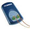
Troubleshooting Thermocouple Input Devices
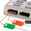
Testing a
thermocouple input measuring device is as simple as connecting a short across the input terminals.
This applies to ALL thermocouple measuring devices, such as plug-in cards, dataloggers, panel meters, hand
held meters, temperature controllers and recorders.
There are many factors that can give a thermocouple measuring device an erroneous reading, such as noise,
ground loops and broken thermocouples. When encountering trouble measuring thermocouples, the first test
should be the SHORT test, since it literally takes minutes and usually answers many questions.
For example, if a thermocouple is connected to a plug-in card (designed for thermocouple inputs), and erratic readings are noticed, it may be the result of a ground loop or
noise induced on the thermocouple wires. It may also be a faulty plug-in card. At this point, there is a lot of uncertainty.
Simply remove the thermocouple and connect a piece of copper wire across the input in its place (also, connect another piece of wire from the (-) to LL Gnd. If you have more than one thermocouple connected, remove ALL of the thermocouples and short all the active inputs. They should all read room temperature, and should be fairly stable.
If the readings are stable and read ambient temperature when shorted, then we know that it is not the card, nor the PC, nor the software, but may be in the wiring or even a broken thermocouple. This will not solve all of your problem, however it is a simple first step that will help to narrow down the possibilities.
If, on the other hand, the readings are still erratic, then it may be the board and it may need to be returned for repair. It would be a good idea to try another PC to eliminate the possibility of a bad PC slot or power supply, etc.
Also, if a custom program is being used, it would be a good idea to test the board with factory supplied software.
If it is determined that the board works fine with a short, then the thermocouple wiring must be checked. Re-connect the thermocouple, and try moving the wiring around a bit.
It is better to go a longer distance and work AROUND a noisy piece of equipment, such as a motor or compressor than to go directly over this equipment. Sometimes, it is necessary to use SHIELDED thermocouple wire, where the shield is connected to a suitable ground on ONE END ONLY.
Sometimes, it is necessary to completely electrically isolate the thermocouple from what you are measuring. If you are inserting a probe into a machine, there may be voltages present which can cause current to flow into the thermocouple right through its steel sheath, causing erratic readings.
The solution is to use UNGROUNDED thermocouples, where the sensor does not touch the sheath, therefore isolating it. This may reduce response time a bit, but will stop any ground loops. If connecting a bare wire to a metal surface, a neat trick would be to use an non-conductive paint and cover the thermocouple tip, making sure the paint can handle your temperature range.
Or, put a small piece of tape on the surface, or use OMEGABOND™ epoxy to isolate the wires. In extreme cases, or areas where tape or paint cannot be used, signal conditioners can be used to isolate a thermocouple up to thousands of volts.
This is the most expensive method however, is the most fool proof, providing electrical isolation, noise filtering and signal amplification as well as safety. Since the signal is amplified to a higher voltage, or even 4-20ma, a less expensive card may be used instead of a thermocouple measuring card.
Drop the Voltage of a Signal So That it Can Be Measured With a Smaller Input Range
In order to measure a signal which varies over a range greater than the input range of an analog or digital input of a measuring device, a voltage divider can drop the voltage of the input signal to the level the analog or digital input can measure.
A voltage divider takes advantage of Ohm's law, which states,
VOLTAGE = CURRENT * VOLTAGE
And Kirkoff's voltage law which states,
THE SUM OF THE VOLTAGE DROPS AROUND A CIRCUIT WIL BE EQUIAL TO THE VOLTAGE DROP FOR THE ENTIRE CIRCUIT.
Any variation in the voltage drop for the circuit as a whole will have a proportional variation in all the voltage drops in the circuit.
A voltage divider takes advantage of the fact that the voltage across one of the resistors in a circuit is proportional to the voltage across the total resistance in the circuit. The trick to using a voltage divider is to choose two resistors with the proper proportions relative to the full scale of the analog or digital input and the maximum signal voltage. The phenomena of dropping the voltage proportionally is often called attenuation. The formula for attenuation is:
A = R1 + R2/ R2
The variable A is the proportional difference between the signal voltage max and the full scale of the analog input.
EXAMPLE 1
If the signal varies between 0-20Vdc and you wish to measure it with an analog input with a full scale range of 0-10Vdc, the attenuation is 2:1 or just 2.
Once you know have determined the attenuation, A, you can calculate for the Resistor R1. For now, pick a value for R2 (typically 10K) and calculate for R1.
R1 = (A - 1) * R2
R1 = (2 - 1) * 10000
R1 = 10000 Ohms
Therefore, R1 and R2 are both 10K resistors. See the connection diagram below for wiring information.
IMPORTANT NOTE: The resistors R1 and R2 are going to dissipate all the power in the divider circuit according to the equation Current = Voltage / Resistance. The higher the value of the resistance (R1 + R2) the less power dissipated by the divider circuit.
 CLOSE
CLOSE
 Aquisição de Dados
 Acquisition de Données
 Adquisición de Datos
 Adquisición de Datos
 Data Acquisition
 Datafangst
 Acquisition de Données
 Datenerfassung
  Acquisizione Dati
 Data Acquisition
 Adquisición de Datos
 Data Acquisition
 Data Acquisition
 数据采集
数据采集 Data Acquisition
 データ取得
データ取得 DAQ
DAQ Data Acquisition
 Data Acquisition
 Data Acquisition
 Data Acquisition
 Data Acquisition