In contrast to analog transducers that sense continuous variables such as pressure and temperature, many transducers provide an output that is one of two states: high or low, open or closed. A pressure might be too high or a temperature too low, triggering closure of a switch. Outputs, too, are not strictly analog-solenoid valves typically are opened or closed, many pumps and heaters are simply turned on or off. Pulse signals are another form of digital I/O, with one rotation of a turbine flowmeter or tachometer corresponding to a single, countable event. Digital I/O also can be used for parallel communications among plug-in expansion cards, and to generate clock and other timing signals.
Already in the binary language of computers, these types of digital, or discrete, inputs and outputs (I/O) are much easier for microprocessor-based data acquisition systems to deal with than analog signals. Similar to analog-to-digital converters used for analog I/O, digital I/O is designed to deal directly with transistor-to-transistor logic (TTL) level voltage changes. TTL typically sets the low voltage level between 0 and 0.8 V and the high voltage level between 2.0 and 5.0 V. Voltage levels between 0.8 and 2.0 V are not allowed. A voltage change, then, from the high range to the low range (or vice versa) represents a digital change of state from high to low, on to off, etc.
And because acquiring an analog signal is more complex than acquiring a digital one, analog I/O channels also are more expensive. Hence, if digital I/O is adequate, do not bother with analog.
Digital Inputs
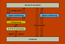
Many types of digital input signals from switch closures, relay contacts, or TTL-compatible interfaces can be read directly by digital I/O cards (Figure 2-1). Other types of inputs may require some signal conditioning, most likely to reduce higher-level voltage changes to TTL levels. A variety of signal conditioning modules are available to provide isolation and other digital conditioning functions.

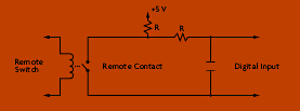
The most common type of digital input is the contact closure (Figure 2-2). Essentially a sensor or switch of some type closes or opens a set of contacts in accordance with some process change. An applied electrical signal then determines whether the circuit is open or closed. Current flows if the circuit is closed, registering a "1" in a transistor at the computer interface. Conversely, an open circuit retains a high voltage (and no current), registering a "0" at the transistor.
Another type of digital input useful in data acquisition applications is the hardware trigger. This allows an external event-a high reactor temperature, perhaps, or a low tank level-to control data collection. If during routine operation data is only being acquired for archival storage on a once-per-second basis, a hardware trigger can be used to boost the data acquisition rate during an upset until normal conditions are restored.

Digital Outputs
At its simplest, a digital output provides a means of turning something on or off. Applications range from driving a relay to turning on an indicator lamp to transmitting data to another computer. For latching outputs, a "1" typically causes the associated switch or relay to latch, while a "0" causes the switch to unlatch. Devices can be turned on or off, depending on whether the external contacts are normally open or normally closed.
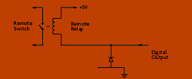
Standard TTL level signals can be used to drive 5-V relay coils; a protective diode is used to protect the digital output circuitry (Figure 2-3).
Because data acquisition boards can typically supply only 24 mA of driving current, they are intended primarily to drive other logic circuits, not final control elements. Scaling may be needed so that logical voltage levels are sufficient to cause switching in larger relays. Outputs intended to drive larger solenoids, contactors, motors, or alarms also may require a boost.

Pulse I/O
A somewhat separate class of digital I/O is pulse inputs and outputs, which typically is associated with frequency, counting, or totalization applications. Pulse inputs might be used to count the rotations of a turbine flowmeter; pulse outputs might be used to drive a stepping motor.
Pulse inputs are handled in much the same way as digital logic inputs, but the output of the sensing circuit is normally connected to a counter rather than a specific bit position in the input register. Successive pulses increment or decrement the counter. Add an elapsed time measure and a frequency or pulse rate can readily be determined. Similar to an analog-to-digital converter, a counter is characterized by its number of bits-an N-bit counter can accumulate up to 2N discrete events. Thus, a 16-bit counter can count to 216 = 65,536.
 CLOSE
CLOSE


