How to Mount Thermocouples Correctly?
Thermocouples come in many styles from direct immersion, to thermowell, to hand-held, to surface mount and many others. Each has a specific way of implementing the sensor, but here are a few things to keep in mind:
- Remember that the only temperature a thermocouple measures is its own temperature. Therefore, the goal is to get the thermocouple measurement junction to the same temperature as the item or process you want to measure.
- Heat always flows from hot to cold, and metal wires, sheaths and housings conduct heat. Therefore, in order to get an accurate measurement in immersion applications it is important that the sensor be immersed sufficiently to negate the conduction of heat up or down the wires and housing. This is known as “Stem Conduction” and is dependent on the process and ambient conditions.
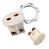
- For surface sensors, many have either mounting holes for fasteners or adhesive surfaces for installation.
- Some thermocouples have mounting threads or other means of installation that are obvious. For other there is a large selection of compression fittings, feedthroughs, brackets and other accessories for mounting these to your process.
Wiring Thermocouples
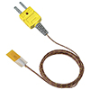
Thermocouples have positive and negative wires, therefore it is important to maintain the polarity during installation. For thermocouples with ANSI/ASTM Color-Codes, the negative wire is always red. In IEC color-coded thermocouples the negative wire is always white.
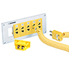
When using extension wire or connectors, the same thermocouple type must be used in order to not introduce an error. Thermocouple connectors have the polarity listed on the connector shell and have unique pin sizes to insure that the connectors are properly combined.
If any of the connections are reversed it will result in an error in the measurement.
Connecting Thermocouples to Other Devices
When connecting thermocouples to other devices care needs to be taken to ensure that the proper polarity is maintained. Thermocouples manufactured to the ANSI/ASTM color-codes always have the negative wire as the red wire. This is opposite the normal electrical standard of positive wire is red. Also, when extension wire is needed, thermocouple wire must be used to maintain accuracy.
The crossing of the polarity, and the use of non-thermocouple wire as extension wire, are two of the most common causes of errors in installing thermocouples.
How to Have One Thermocouple Feeding Two Devices
If more than one measurement is needed, then dual or multiple thermocouples should be used. In dual thermocouples, separate measuring circuits are contained in the sensor so that each thermocouple signal is independent of the other. This insures that one measurement signal does not have an adverse effect on the other.
Transferring Signal
Thermocouple signals are low-voltage signals that are easily affected by electro-magnetic noise. High voltage devices and electro-magnetic emitters such as motors and radios can get into the thermocouple signal and overwhelm it. In cases with long cable runs are needed, or where electro-magnetic interference is expected, shielded cable can be used to help protect the thermocouple signal from these sources.
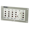
A better option for many is the use of temperature transmitters or signal conditioners. These devices can be located close to the sensor and will not only convert the low-voltage signal to a 4-20 milliamp or other more robust signal, but will also provide the reference junction.
The question of how long a thermocouple cable can be is more a function of the capability of the measurement instrument.
Diagnosing Temperature Reading Errors with Thermocouples
When investigating reading errors here are some places to start:
- Thermocouples have positive and negative wires so when connecting them you need to make sure that the polarity of the connections is correct. This also holds true when adding extension wires to the circuit. Remember the red wire is negative when using ANSI/STM color-coded thermocouples (white for IEC color-coded thermocouples).
- When extension wire is used to connect a thermocouple to its measuring instrument, the same thermocouple type wire must be used otherwise errors will occur.
- Thermocouples require what is called a cold junction reference at the instrument end of the circuit. Most thermocouple instruments include this, but if you are using a millivolt meter this needs to be considered.
- Electrical noise can cause measurement errors especially when using grounded thermocouples.
Thermocouple Installations | Related Products
↓ View this page in another language or region ↓
 CLOSE
CLOSE
 Thermocouple Installations
 Thermocouple Installations