 CLOSE
CLOSE
An LVDT (linear variable differential transformer= is an electromechanical sensor used to convert mechanical motion or vibrations, specifically rectilinear motion, into a variable electrical current, voltage or electric signals, and the reverse. Actuating mechanisms used primarily for automatic control systems or as mechanical motion sensors in measurement technologies. The classification of electromechanical transducers includes conversion principles or types of output signals.
In short, a linear transducer provides voltage output quantity, related to the parameters being measured, for example, force, for simple signal conditioning. LVDT Sensor devices are sensitive to electromagnetic interference. Reduction of electrical resistance can be improved with shorter connection cables to eliminate significant errors. A linear displacement transducer requires three to four connection wires for power supply and output signal delivery.
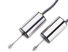
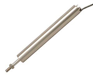
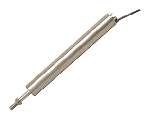
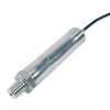
Physically, the LVDT construction is a hollow metallic cylinder in which a shaft of smaller diameter moves freely back and forth along the cylinder’s long axis. The shaft, or pushrod, ends in a magnetically conductive core which must be within the cylinder, or coil assembly, when the device is operating.
In common practice, the pushrod is physically attached to the moveable object whose position is to be determined (the measurand), while the coil assembly is attached to a fixed reference point. Movement of the measurand moves the core within the coil assembly; this motion is measured electrically.
- Electromagnetic
- Magnetoelectric
- Electrostatic
- Analog and discrete output
- Digital
- Static and dynamic qualities
- Sensitivity or transfer ratio - E=Δy / Δx or Δy is the change in output quantity y when input quantity x is changed by Δx
- Output signal—range of operating frequency
- Static error of conversion or of the signal
Types of LVDTs
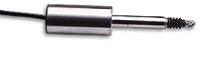
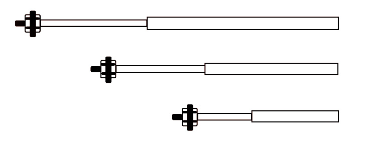
Captive Armatures: These mechanisms are better for long working ranges. Captive armatures help prevent misalignment because they are guided and restrained by low friction assemblies.
Unguided Armatures: Infinite resolution qualities, the unguided armature LVDT mechanism is a no-wear design that doesn’t restrict the resolution of measured data. This mechanism type is attached to the specimen to be measured, fitting loosely in the tube, requiring the body of the linear transducer to be supported separately.
Force-Extended Armatures: Use internal spring mechanisms, pneumatic force, or electric motors to push the armature continuously to its fullest extension possible. Force-extended armatures are used in LVDT’s for slow moving applications. These mechanisms require no connection between the specimen and armature.
Linear Variable Displacement Transducers are commonly used in modern machining tools, avionics, robotics, and computerized or motion control, Automation manufacturing. The selection of an applicable type of LVDT can be considered using the following specifications:
LVDT linearity: Maximum deviation from direct proportion between distance measured and output distance over measuring range.
> 0.025 ± % Full Scale
0.025 - 0.20 ± % Full Scale
0.20 - 0.50 ± % Full Scale
0.50 - 0.90 ± % Full Scale
0.90 - ± % Full Scale & Up
Operating Temperatures: > -32ºF, -32 to 32ºF, 32 to 175ºF, 175 to 257ºF, 257ºF and up. Range of temperature within which the device must accurately operate.
Measurement Ranges: 0.02", 0.02 to 0.32", 0.32 to 4.0", 4.0 to 20.0", ±20.0" (range of measurement or maximum distance measured)
LVDT accuracy: Describes percentage of deviation from the actual/real value of measurement data.
Output: Voltage, Current, or Frequency
Interface: Serial—Standard digital output protocol (serial) like RS232, or Parallel—Standard digital output protocol (parallel) like IEEE488.
Type of LVDT: Current Balance AC/AC, or DC/DC, or Frequency Based
Displacement:
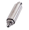
A linear displacement transducer is an electrical transducer used in measuring linear position. Linear displacement is the movement of an object in one direction along a single axis. Measuring displacement indicates the direction of motion. The output signal of the linear displacement sensor is the measurement of the distance an object has traveled in units of millimeters (mm), or inches (in.), and can have a negative or positive value.Precision manufactured LVDT displacement transducers are mounted on most modern product lines for automatic gaging in sorting, “go-no go” applications, and quality operations. Construction of hardened steel shafts, O-ring seals, and titanium push rods optimize precision function in most industrial conditions. Utilizing hybrid IC modules provide linear mV/V/mm or mV/V/inch output to interface with standard DC input meters, industrial controllers, recorders, and data interfaces.
- General Purpose
- Aerospace
- Flush Diaphragm
- Heavy Duty/Industrial
- Hazardous Location
- PC Board Mountable
- High Accuracy
- Submersible
- Sanitary
- Customized for Special Purposes
This differential design gives the LVDT significant advantage over potentiometer-type devices, in that resolution is not limited by the spacing of coil windings. In an linear transducer any movement of the core causes a proportional change in output. The LVDT thus has theoretically infinite resolution: in practice, resolution is limited only by the external output electronics and the physical suspensions.
Because it is a transformer, the LVDT requires an ac drive signal. A dedicated electronics package, or signal conditioner, is generally used to generate this drive signal, and also to convert the device’s analog ac output to +5Vdc, 4-20mA or some other format compatible with downstream equipment. This circuitry may be external, or it may be housed within the transducer body. Internal electronics allow the user to feed the transducer a dc signal of only moderate quality, often a benefit in battery-powered and onboard vehicular applications. However, external electronics offer higher quality and may provide optional features such as calibration to enable direct readout in engineering units.
How does the LVDT work?
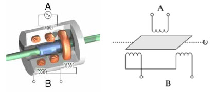
A typical LVDT sensor has three solenoid coils lined end-to-end, surrounding the tube. Primary coil is in the center and secondary coils are top and bottom. The object of position measurement is attached to the cylindrical ferromatic core, and slides along the axis of the tube. Alternating current drives the primary coil causing voltage induced in the two secondary coils proportionate to the length of the linking core. Range of frequency is usually from 1 to 10 kHz.
Movement of the core triggers the linkage from primary to both the secondary coils, which changes the induced voltages. Top and bottom secondary output voltage differential is the movement from calibrated zero phase. Using a synchronous detector reads a signed output voltage that relates to the displacement. LVDT linear transducers can be up to several inches long, working as an absolute position sensor which is repeatable and reproducible. Other actions or movements will not alter measurement accuracy. The LVDT is also highly reliable because the sliding core does not touch the inside of the tube, and allows the sensor to be in a completely sealed environment.
The LVDT is an ac device which means there is a need for electronics to translate its output into a useful dc signal. There are two hybrid modules that are the foundation for LVDT Signal Processing; an Oscillator and a Demodulator.
The Oscillator is designed to provide a stable sine wave for driving the transducer, and a square wave reference for the Demodulator. The Demodulator is designed to amplify the output from the transducer, and convert it into a highly accurate dc voltage which is directly proportional to displacement.
To operate the linear transducer, it is necessary to drive the primary with a sine wave and the output from the secondaries consist of a sine wave with the position information contained in the amplitude and phase. The output at the center of the stroke is zero, rising to maximum amplitude at either end of the stroke. The output is in phase with the primary drive at one end of the stroke and out of phase at the other end.
In a high quality linear displacement transducer, the relationship between position and phase/amplitude is linear. The Oscillator and Demodulator are what makes the transition between position and phase/amplitude easy.
Description of the oscillator
The function of the Oscillator is to provide an accurate sine wave voltage to drive the transducer, stable in both amplitude and frequency. It also provides a square wave phase reference to the reference for use internally and for setting zeroes in the Demodulator. The Oscillator works as follows. The sine wave to drive the transducer is generated by an internal high stability Wien Bridge Oscillator. The frequency of the oscillator is set by linking pins or adding external resistors. The sine wave is then passed through a power amplifier to provide sufficient current to drive most transducers (50mA) without the need for external buffers. The power amplifier contains protection circuitry as short circuits are likely in the environment where most transducers work.The sine wave is output to the transducer and is used internally to generate a square wave for phase referencing the Demodulator. The Oscillator output is monitored by the remote sense input, which enables allowance to be made for voltage drops in the transducer leads. This input is sampled by the square wave and compared to the reference input in the amplitude regulator to hold the Oscillator voltage to a fixed level. The reference input is taken from the reference output or ratiometric output. enabling the Oscillator voltage to be fixed or proportional to the supply voltage.
Description of the demodulator
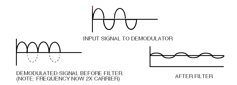
The function of the Demodulator is to take the AC output of the transducer and convert it into a useful dc voltage proportional to displacement, load etc. It also contains circuitry to enable the adjustment of Gain and Zero to accommodate a wide range of transducers.The Demodulator works as follows. The output from the transducer is fed into a coarse gain select circuit and is then amplified. This amplifier can have a gain of 25 or 250 if the x10 option is used, the extra gain allowing operation with low output transducers such as strain gauges.
Doing the main amplification with the ac signal means that the drift of the circuit is reduced. The high level ac signal is then passed to a phase synchronous Demodulator, which uses the square wave from the Oscillator to convert it into a dc voltage with some superimposed ac. This is then fed through a low pass filter which removes the majority of the ac components leaving a steady dc voltage with slight ripple. The low pass filter includes circuitry for setting coarse zero, fine zero and fine gain, and also has connections so that the filter characteristics can be altered.
Innovations and Applications for the linear transducer
LVDT Rig is Better For Tensile Test Measurements
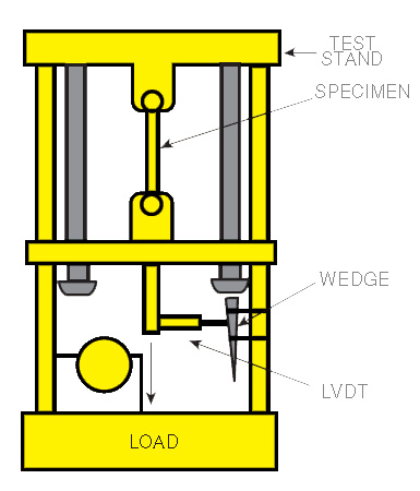
When tensile testing a material to determine its modulus of elasticity it is necessary to know precisely the applied load and the distance that the material stretches under that load. Traditionally, these parameters are accurately measured using a load cell and LVDT displacement transducer respectively. In the latter cases, an extensometer-incorporating the displacement transducer—is connected directly to the sample under test.This method has two distinct disadvantages:
- the extensometer has to be set up for each sample and tends to restrict access to it.
- if the sample is tested to breaking point, the sudden shock can damage the transducer.
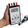
With this alternative method, the gauging linear transducer is fixed to the sample securing clamp which moves as the material stretches. As the gauging transducer sensing head travels up the inclined surface of the wedge, the vertical movement is transferred to a proportional horizontal movement of the transducer core. The linear voltage output signal from the transducer is fed to a digital voltmeter or similar measuring device, which can be calibrated with reference to the angle of the inclined surface to give a direct and precise measurement of the elongation of the material under load.
Gauging transducers have highly accurate linear outputs, even for small strokes, so that the calibrated measurement of the test sample’s elongation is also very accurate. For very small elongations, e.g. less than 1 mm under high applied loads, an extensometer using an linear displacement transducer will be marginally more accurate. However, the gauging transducer device is preferable for most applications and it is especially suitable when testing materials such as soft metals, plastics and rubber that stretch by significant amounts without breaking.
Because the gauging transducer is fixed to the side of the clamp, it does not obstruct access to the test sample. Also it does not require to be set up every time a new sample is placed in the testing machine. If the sample breaks, the transducer tip simply moves more quickly along the incline without risk of damage. The overall design is very compact.
Transducers Shape up to Changing Material Thickness
Gauging transducers are commonly used in industry to check that the thickness of a manufactured sheet material such as paper or metal remains within the specified tolerances. Where the profile of the measurand product involves several different thicknesses, such as a complex extrusion, a gauging rig can be devised incorporating a number of linear transducers to monitor the various dimensions. In a further variation on this idea, LVDT type gauging transducers have been built into a rig designed to measure the varying thickness of a natural manufacturing material — processed animal skins. These profile measurements are then used to build up a picture of a complete skin, so that areas of uniform thickness can be cut from it and used to best advantage; the thinnest leather being selected perhaps for gloves, the somewhat thicker areas for handbags and so on.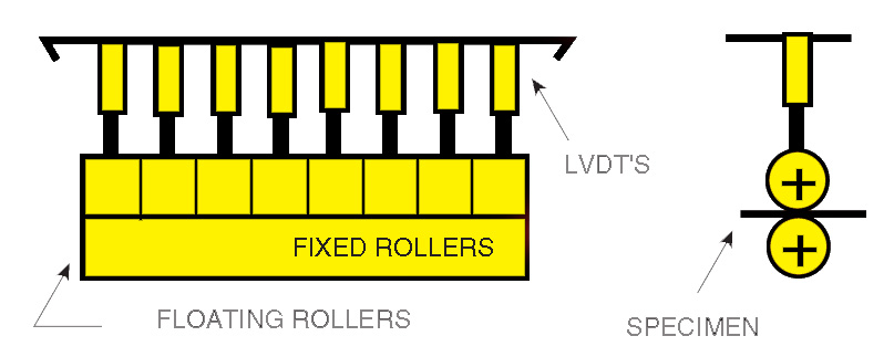
Each section is spring loaded against a common supporting spindle, which is set at a fixed distance above the datum roller. As the skin passes between the rollers, the sections of the upper roller are held in positive contact with the material surface by the springs, yet they are able to move up and down as the skin thickness varies. A separate LVDT gauging transducer is dedicated to each roller section and monitors the changing skin thickness at that point. To avoid any sideways straining of the transducer sensing head, that might be caused by direct contact with the rotating roller, the vertical displacement is transmitted mechanically to the transducer by a pivoted flat bar, which rests with its free end on top of the roller (see side view diagram).
The voltage output signal from the transducer is calibrated at the measuring device to take account of the fact that the distance moved by the transducer head with this arrangement differs slightly from the actual vertical movement of the roller section. Height of the upper roller support spindle is set to suit an average skin thickness. The number and width of roller sections were designed to suit the widest skin expected. As the skin passes between the rollers, the recorded measurements give a precise indication of the varying skin thickness along the line of each transducer.
A “contour map” of the whole skin, showing the areas of different thickness, is generated by processing the linear transducer output signals in a computer and presenting the resulting data. Color codes or monochrome tones can be used to clarify the areas of different thicknesses, just as various land heights are denoted on a normal map.
Any section of the skin of a required thickness can be easily identified for manufacture of specific items, thus facilitating positioning of the patterns and making optimum use of the material with minimal wastage.
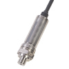
Using linear Displacement Transducers to Measure Pressure and Load
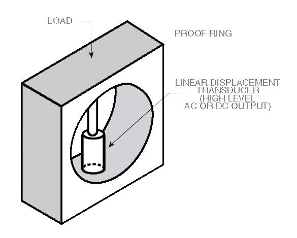
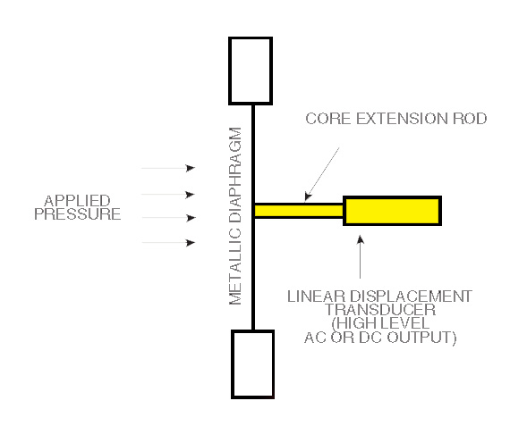
One application for the diaphragm system is the measurement of pressure inside a containment, such as engine cylinder block pressure during development and testing. Mounted inside a proof ring, the displacement transducer can offer advantages over the strain gauge for measuring very small loads or if there is a possibility of shock loading. Typically the convoluted metallic diaphragm is built into the wall of the pressurized vessel and deflects under pressure. Diaphragm thickness and sensitivity are designed to suit the pressure range.
The LVDT linear transducer is mounted at right angles to the diaphragm with its core extension rod attached to the center of the disc. Linear transducers are available for operating temperatures up to 600°C.
Alternatively for high temperatures, a proximity transducer can be used, which does not make contact with the diaphragm. Any flexing of the diaphragm is reflected by the output voltage signal from the transducers. A simple microchip can be used to calibrated simply by pressurizing to one known high pressure and one low pressure, since the disc movement is linear with pressure at the center. The resulting low-cost, simple pressure sensor is highly repeatable and reliable.
Although the proof ring flexes, it is in fact more robust and resilient than the strain gauge. Stiffness in a strain gauge has an advantage when the load is applied and removed rapidly, since the stiff system gives a high frequency response. If the strain gaugeºº is subject to high shock loading, however, it can be easily overloaded. A proof ring on the other hand, can move farther to absorb the shock load without detrimental effect.
Using a LVDT sensor for Counting
High speed counting of bank notes—or similar sheet items requiring absolute numerical accuracy—can be achieved by means of a simple design principle based on linear transducers. The voltage signal output from these highly sensitive LVDT sensors can be used to: count the notes individually at high speed; detect when two or more notes are counted together; identify a taped repair; indicate when a note has become folded over; and alert the operator when part of a note is missing.In typical machine design, the notes are fed between two rotating rollers, one of which runs in fixed bearings while the other is able to move linearly to vary the gap between them. The latter roller is held in positive contact with the bank note by suitable loading. A miniature linear transducer is mounted at each end of this moveable roller to measure its linear displacement as the notes pass through the gap.
Consequently, when a single bank note passes between the rollers, the LVDT cores are displaced by an amount equal to the thickness of the note, and this produces voltage output signals of a corresponding intensity for both transducers. The signal is sustained only while the note is passing between the rollers and thus produces a pulse output which can be used for electronic counting. Two notes passing through together will double the sustained signal intensity, and so on.
Other Applications
Power Turbines: Power generation turbine applications for power plants around the world use linear variable differential transducers as position sensors with signal conditioners to provide the necessary operating power. The AC voltages and frequencies needed for inductive or LVDT types of position sensors are not available from power line sources.Hydraulics: Linear position sensors serve as charge sensors in hydraulic accumulators, special external sensors in harsh environments with high immunity to vibration and shock, and includes all stroke lengths within our sensor capabilities. If you require longer stroke lengths, call our professional engineering staff at OMEGA, for custom design information.
Automation: LVDT automation applications make use of hermetically sealed dimensional gaging probes to perform beyond your R & D laboratories, fabrication workshops, an into the harsh environmental working conditions of factory automation, process control environments, TIR measurements, and industrial gaging.
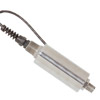
Aircraft: The majority of aerospace/aircraft applications use miniature or sub-miniature position transducers. They are cable-actuated displacement sensing mechanisms. OMEGA can develop precision products for applications in commercial aircraft, space, aviation and environmental systems for space habitats. Products are mounted to a fixed position, the displacement cable is attached to a moving object like landing gear or an aileron. The cable retracts and extracts when movement occurs. Depending on signal conditioning, and mounting system, the electrical output will indicate various rates, angles, lengths, and motions.
Satellites: Consider the applications in satellite technology and related areas, in addition to satellite production, position transducers are needed for space vehicles, cargo aircraft, military fighters, drones, experimental aircraft, missiles, nuclear reactors, flight simulators, or high speed railways.

 In the airline industry weight is money. Every additional pound requires more fuel to lift...
 How to use strain gauges and optimize their performance while working with inhomogeneous materials
 Understand the necessary criteria to select the right type of pressure transducer for your application