Types of Stepper Motors
There are three basic types of stepper motors:
- Active rotor: permanent magnet step motor(PM)
- Reactive rotor: variable reluctance stepper motor(VR)
- Combination of VR and PM: Hybrid stepper motor (HY)
These are brushless electrical machines which rotate in fixed angular
increments when connected to a sequentially switched DC current.
When alternating current is used, the rotation is essentially
continuous.
Permanent Magnet stepper motor
This type of stepper motor has a permanent magnet rotor. The stator
can be similar to that of a conventional 2- or 3-phase induction
motor or constructed similar to a stamped motor. The latter is the
most popular type of stepper motor.
a.) Conventional permanent magnet type. Figure 1 shows a diagram of a conventional
permanent magnet rotor stepper motor. A 2-phase winding
is illustrated. Figure 1a shows Phase A
energized with the “A” terminal positive. The field is at 0°.
With the coil wound as shown, the north seeking pole of the
rotor is also at 0°.
The shaft completes one revolution for each complete revolution
of the electromagnetic field in this motor. Figure 2 shows the same stepper motor with both windings energized. The important
difference here is that the resultant electromagnetic field is between
two poles. In Figure 2, the field has moved 45° from
the field in Figure 1.
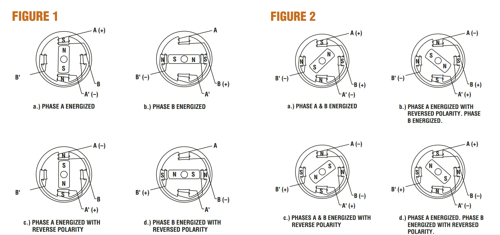
As in the one-phase-on energizing scheme, the shaft completes one
revolution for each complete revolution of the electromagnetic field.
It should be evident that this motor can half step; i.e., step in small
step increments. This is possible by combining the energization
shown in Figure 1 with that shown in Figure 2. Figure 3 shows the diagrams of a
PM stepper motor with half-step rotor motion.
As in the previous diagrams, the rotor and shaft move through the
same angle as the field. Note that each step resulted in a 45° rotation
instead of 90° in the previous diagram.
A permanent magnet stepper motor may be wound with a bifilar
winding to avoid the necessity of reversing the polarity of the
winding. Figure 4 shows the bifilar winding while
Table IV shows the energization sequence.

Bifilar windings are easier to switch using a transistor controller.
Fewer switching transistors are required.
b.) Stamped or can stack permanent magnet stepper motor. The
most popular type of permanent magnet stepper motor is the so
called stamped type, claw tooth, sheet metal, tin can or simply
low cost motor. This motor is difficult to illustrate clearly
because of the way it is constructed.
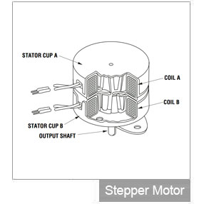
This motor has a pair of coils surrounding a permanent magnet rotor.
The coils are enclosed in a soft iron housing with teeth on the
inside reacting with the rotor. Each coil housing has the same
number of teeth as the number of rotor poles. The housings are
radially offset from each other by one-half the tooth pitch.
Variable reluctance stepper motor
This type of stepper motor has an electromagnetic stator with a
magnetically soft iron rotor having teeth and slots similar to the
rotor of an inductor alternator. Whereas PM motors are basically
2-phase machines, VR motors require at least 3 phases. Most VR
stepper motors have 3 or 4 phases although 5-phase VR motors are
available.
In a VR stepper motor, the field moves at a different rate than the rotor.
Note that Phase A coil has two
south poles and no north poles for a flux return path. You may rest
assured that there will be one. The flux will return through the path
of least reluctance, namely through the pole pairs which are nearest
to two rotor teeth. This varies with rotor position. The flux induces a
voltage in the coils wound on the pole. This induces a current in the
winding slowing the rotor. The amount of current is determined by
the voltage across the coil. A diode-clamped coil will have more
current than a resistor diode or zener diode-clamped winding.
Hybrid stepper motor
This type of motor is frequently referred to as a permanent magnet
motor. It uses a combination of permanent magnet and variable
reluctance structure. Its construction is similar to that of an
induction motor.
The rotor has two
end pieces (yokes) with salient poles equally spaced but radially
offset from each other by one-half tooth pitch. A circular permanent
magnet separates them. The yokes have essentially uniform flux
of opposite polarity. The stator is formed from laminated steel.
Some motors have 4 coils arranged
in two groups of 2 coils in series. One coil pair is called Phase A and
the other Phase B.
The number of full steps per revolution may be determined from the
following formula:
SPR = NR x Ø
Where: SPR = number of steps per revolution
NR = total number of rotor teeth (total for
both yokes)
Ø = number of motor phases
or: NR = SPR/Ø
They are constructed with multi-toothed stator poles and a permanent magnet rotor. Standard hybrid motors have 200 rotor teeth and rotate at 1.8º step angles. Because they exhibit high static and dynamic torque and run at very high step rates, hybrid stepper motors are used in a wide variety of commercial applications including computer disk drives, printers/plotters, and CD players.
Step Modes
Stepper motor "step modes" include Full, Half and Microstep. The type of step mode output of any stepper motor is dependent on the design of the controller. Omegamation™ offers stepper motor drives with switch selectable full and half step modes, as well as microstepping drives with either switch-selectable or software-selectable resolutions.
Full Step
Standard hybrid stepping motors have 200 rotor teeth, or 200 full steps per revolution of the motor shaft. Dividing the 200 steps into the 360° of rotation equals a 1.8° full step angle. Normally, full step mode is achieved by energizing both windings while reversing the current alternately. Essentially one digital pulse from the driver is equivalent to one step.
Half Step
Half step simply means that the stepper motor is rotating at 400 steps per revolution. In this mode, one winding is energized and then two windings are energized alternately, causing the rotor to rotate at half the distance, or 0.9°. Although it provides approximately 30% less torque, half-step mode produces a smoother motion than full-step mode.
Microste
Microstepping is a relatively new stepper motor technology that controls the current in the motor winding to a degree that further subdivides the number of positions between poles.
Omegamation microstepping drives are capable of dividing a full step (1.8°) into 256 microsteps, resulting in 51,200 steps per revolution (.007°/step). Microstepping is typically used in applications that require accurate positioning and smoother motion over a wide range of speeds. Like the half-step mode, microstepping provides approximately 30% less torque than full-step mode.
Linear stepper motor Control
The rotary motion of a stepper motor can be converted to linear motion using a lead screw/worm gear drive system (See figure B). The lead, or pitch, of the lead screw is the linear distance traveled for one revolution of the screw. If the lead is equal to one inch per revolution, and there are 200 full steps per revolution, then the resolution of the lead screw system is 0.005 inches per step. Even finer resolution is possible by using the stepper motor/drive system in microstepping mode.
Series vs. Parallel Connection
There are two ways to connect a stepper motor, in series or in parallel. A series connection provides a high inductance and therefore greater torque at low speeds. A parallel connection will lower the inductance which results in increased torque at faster speeds.
Stepper motor controller Technology Overview
The driver receives step and direction signals from the indexer or stepper motor controller and converts them into electrical signals to run the stepper motor. One pulse is required for every step of the motor shaft.
In full step mode, with a standard 200-stepper motor, 200 step pulses are required to complete one revolution. The speed of rotation is directly proportional to the pulse frequency. Some control systems have an on-board oscillator which allows the use of an external analog signal or joystick to set the motor speed.
Speed and torque performance of the stepper motor is based on the flow of current from the driver to the motor winding. The factor that inhibits the flow, or limits the time it takes for the current to energize the winding, is known as inductance. The effects of inductance, most types of control circuits are designed to supply a greater amount of voltage than the motor's rated voltage.
The higher the output voltage from the controller, the higher the level of torque vs. speed. Generally, the driver output voltage (bus voltage) should be rated at 5 to 20 times higher than the motor voltage rating. In order to protect the motor from being damaged, the stepper motor drive should be current-limited to the stepper motor current rating.
Stepper motor Controller Overview
The indexer, or stepper motor controller, provides step and direction outputs to the driver. Most applications require that the indexer manage other control functions as well, including acceleration, deceleration, steps per second and distance. The indexer can also interface to and control many other external signals.
Communication to the control system is through an RS-232 serial port and in some cases an RS485 port. In either case, the stepper motor controller is capable of receiving high-level commands from a host computer and generating the necessary step and direction pulses to the driver.
The controller includes auxiliary I/O for monitoring inputs from external sources such as a Go, Jog, Home or Limit switch. It can also initiate other machine functions through the I/O output pins.
Stand-Alone Operation
In a stand-alone mode the controller can operate independent of the host computer. Once downloaded to the non-volatile memory, motion programs can be initiated from various types of operator interfaces, such as a keypad or touchscreen, or from a switch through the auxiliary I/O inputs.
A stand-alone stepper motor control system is often packaged with a driver and power supply and optional encoder feedback for "closed loop" applications that require stall detection and exact motor position compensation.
Multi-Axis Control
Many motion applications have more than one stepper motor to control. In such cases a multi-axis stepper motor controller is available. A HUB 444 networking hub, for example, may have up to four stepper drives connected to it, with each drive connected to a separate stepper motor. The networking hub provides coordinated movement for applications requiring a high degree of synchronization, such as circular or linear interpolation.
 CLOSE
CLOSE
 Step and Direction
 Oscillator
 Stand-Alone Programmable
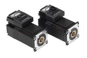
 High Performance Stepper Motors
 Motores de Passo
 Moteurs pas à pas
 Stepper Motors
 Moteur pas à pas
 Schrittmotoren
 Stepper Motor
 Stepper Motor
 Stepper Motors
 Stepper Motors
 스테퍼 모터
 Stepper Motors
 Stepper Motors
 Stepper Motors
 Stepper Motors
 Stepper Motors