Fiber optics are essentially light pipes, and their basic operation may be traced back more than a century when British Physicist John Tyndall demonstrated that light could be carried within a stream of water spouting out and curving downward from a tank.
A thin glass rod for optical transmission was the basis of a 1934 patent awarded to Bell Labs for a "Light Pipe." American Optical demonstrated light transmission through short lengths of flexible glass fibers in the 1950s. However, most modern advances in fiber optics grew out of Corning Glass developments in glass technology and production methods disclosed in the early 1970s.
Like many technical developments since WWII, fiber optics programs were largely government funded for their potential military advantages. Projects primarily supported telecommunications applications and laser fiber ring gyroscopes for aircraft/missile navigation. Some sensor developments were included in manufacturing technology (Mantech) programs as well as for aircraft, missile and shipboard robust sensor developments. More recently the Dept. of Energy and NIST have also supported various fiber optic developments.
| Relative Transmission Losses for Digital Data |
| |
Losses in dB/km |
| 1.5Mb/s |
6.3Mb/s |
45Mb/s |
| 26 gage twisted wire pair |
24 |
48 |
128 |
| 19 gage twisted wire pair |
10.8 |
21 |
56 |
| RG 217/u coaxial cable |
2.1 |
4.5 |
11 |
| Optical fiber 0.82 um wavelength carrier |
3.5 |
3.5 |
3.5 |
Commercial telecommunications has evolved as the fiber optics technology driving force since the mid-'80s. Increased use of fiber optics well correlates with fiber materials developments and lower component costs. Advances in glass fibers have led to transmission improvements amounting to over three orders of magnitude since the early Corning Glass efforts. For example, ordinary plate glass has a visible light attenuation coefficient of several thousand dBs per km. Current fiber optic glasses a kilometer thick would transmit as much light as say a 1/4" plate glass pane. Table 5-1 indicates relative digital data transmission losses for copper and fiber.
Fiber Advantages
Improved glass transmissions have resulted in undersea cables with repeaters required about every 40 miles--ten times the distance required by copper. Bandwidth and robustness have led to cable service providers selecting fiber optics as the backbone media for regional multimedia consumer services. The world market for fiber optic components was in the USD$4 billion range in 1994 and is projected to reach USD$8 billion in 1998.

Whether used for communications or infrared temperature measurement, fiber optics offer some inherent advantages for measurements in industrial and/or harsh environments:
Unaffected by electromagnetic interference (EMI) from large motors, transformers, welders and the like;
Unaffected by radio frequency interference (RFI) from wireless communications and lightning activity;
Can be positioned in hard-to-reach or view places;
Can be focused to measure small or precise locations;
Does not or will not carry electrical current (ideal for explosive hazard locations);
Fiber cables can be run in existing conduit, cable trays or be strapped onto beams, pipes or conduit (easily installed for expansions or retrofits); and,
Certain cables can handle ambient temperatures to over 300°C--higher with air or water purging.
Any sensing via fiber optic links requires that the variable cause a modulation of some type to an optical signal--either to a signal produced by the variable or to a signal originating in the sensing device. Basically, the modulation takes the form of changes in radiation intensity, phase, wavelength or polarization. For temperature measurements, intensity modulation is by far the most prevalent method used.
The group of sensors known as fiber optic thermometers generally refer to those devices measuring higher temperatures wherein blackbody radiation physics are utilized. Lower temperature targets--say from -100°C to 400°C--can be measured by activating various sensing materials such as phosphors, semiconductors or liquid crystals with fiber optic links offering the environmental and remoteness advantages listed previously.
Fiber Applications
Fiber optic thermometers have proven invaluable in measuring temperatures in basic metals and glass productions as well as in the initial hot forming processes for such materials. Boiler burner flames and tube temperatures as well as critical turbine areas are typical applications in power generation operations. Rolling lines in steel and other fabricated metal plants also pose harsh conditions which are well handled by fiber optics.
Typical applications include furnaces of all sorts, sintering operations, ovens and kilns. Automated welding, brazing and annealing equipment often generate large electrical fields which can disturb conventional sensors.
High temperature processing operations in cement, refractory and chemical industries often use fiber optic temperature sensing. At somewhat lesser temperatures, plastics processing, paper making and food processing operations are making more use of the technology. Fiber optics are also used in fusion, sputtering, and crystal growth processes in the semiconductor industry.
Beyond direct radiant energy collection or two-color methods, fiber optic glasses can be doped to serve directly as radiation emitters at hot spots so that the fiber optics serve as both the sensor and the media. Westinghouse has developed such an approach for distributed temperature monitoring in nuclear reactors. A similar approach can be used for fire detection around turbines or jet engines. Internal "hot spot" reflecting circuitry has been incorporated to determine the location of the hot area.
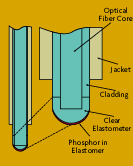
An activated temperature measuring system involves a sensing head containing a luminescing phosphor attached at the tip of an optical fiber (Figure 5-1). A pulsed light source from the instrument package excites the phosphor to luminescence and the decay rate of the luminescence is dependent on the temperature. These methods work well for non-glowing, but hot surfaces below about 400°C.

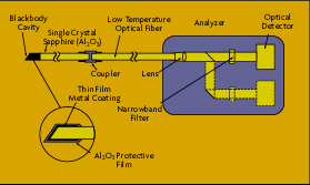
A sapphire probe developed by Accufiber has the sensing end coated by a refractory metal forming a blackbody cavity. The thin, sapphire rod thermally insulates and connects to an optical fiber as is shown in Figure 5-2. An optical interference filter and photodetector determines the wavelength and hence temperature.
Babcock & Wilcox has developed a quite useful moving web or roller temperature monitoring system which will measure temperatures from 120°C to 180°C across webs up to 4 meters (13 ft.) wide (Figure 5-3). The system combines optical and electronic multiplexing and can have as many as 160 individual pickup fibers arranged in up to 10 rows. The fibers transfer the radiation through a lens onto a photodiode array.
Component Options
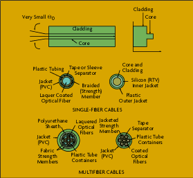
Fiber optics for temperature measurements as well as for communications depends on minimizing losses in the light or infrared radiation being transmitted. Basics of light conduction (Figure 5-4) is a central glass fiber which has been carefully produced to have nearly zero absorption losses at the wavelengths of interest. A cladding material with a much lower index of refraction reflects all non-axial light rays back into the central fiber core so that most of the conducted radiation actually bounces down the length of the cable. Various metal, Teflon or plastics are used for outer protective jackets.

The difference in refractive indices of the core and cladding also identify an acceptance cone angle for radiation to enter the fiber and be transmitted. However, lenses are often used to better couple the fiber with a target surface.
For relatively short run temperature sensing, losses in the fiber optic link are generally negligible. Losses in connectors, splices and couplers predominate and deserve appropriate engineering attention. Along with the fiber optic cable, a temperature measuring system will include an array of components such as probes, sensors or receivers, terminals, lenses, couplers, connectors, etc. Supplemental items like blackbody calibrators and backlighter units which illuminate actual field of view are often needed to ensure reliable operation.
 CLOSE
CLOSE


