 CLOSE
CLOSE
Fiber-optic probes are among the more interesting temperature measurement devices in current use. Here’s the way one company’s products work.
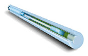
Fiber-optic temperature sensors are based on the light absorption/ transmission properties of gallium arsenide (GaAs). The effects of temperature variations on this semiconducting crystal are well known and predictable. At the measurement end of the fiber-optic temperature sensor (see Figure 1) is a GaAs crystal. As the crystal’s temperature increases, its transmission spectrum (i.e., the light that is not absorbed) shifts to higher wavelengths. At any given temperature, transmission jumps from essentially 0% to 100% at a specific wavelength. This jump is called the absorption shift (see Figure 2). The relationship between the temperature and the specific wavelength at which the absorption shift takes place is very predictable.
Fiber-optic temperature sensors are based on the light absorption/ transmission properties of gallium arsenide (GaAs). The effects of temperature variations on this semiconducting crystal are well known and predictable. At the measurement end of the fiber-optic temperature sensor (see Figure 1) is a GaAs crystal. As the crystal’s temperature increases, its transmission spectrum (i.e., the light that is not absorbed) shifts to higher wavelengths. At any given temperature, transmission jumps from essentially 0% to 100% at a specific wavelength. This jump is called the absorption shift (see Figure 2). The relationship between the temperature and the specific wavelength at which the absorption shift takes place is very predictable.
In addition to the model shown here, the fiber-optic temperature probes are available in a variety of materials and performance specs, each designed to satisfy particular application requirements.
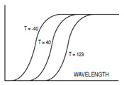
Fiber-optic temperature sensors operate on the absorption/ transmission properties of gallium arsenide crystal semiconductors. Increases in the crystal’s temperature have the effect of shifting its transmission spectrum to higher wavelengths, jumping from essentially 0% to 100% at a specific wavelength. The three temperatures shown here are in ºC.
To understand why the absorption shift occurs, it is necessary to look at the variation in the semiconductor’s energy band gap. This band gap refers to the energy required to bump the electrons in the material from a relaxed, steady state into an excited state. As more energy in the form of heat enters the crystal, the band gap becomes narrower—less additional energy is needed to excite an electron.
The photons entering the crystal are what actually excite the electrons. If a photon is carrying enough energy to get an electron across the gap, it will be absorbed. If it is not carrying enough energy, the photon will be transmitted. The shorter a photon’s wavelength, the more energy it carries. Because the band gap narrows as the crystal’s temperature increases, and less energy is needed to jump the gap, photons with less and less energy (longer and longer wavelengths) are absorbed by the band. The effect is to move the absorption shift to longer wavelengths. Consequently, measuring the position of the absorption shift gives a measure of the crystal’s temperature.
The photons entering the crystal are what actually excite the electrons. If a photon is carrying enough energy to get an electron across the gap, it will be absorbed. If it is not carrying enough energy, the photon will be transmitted. The shorter a photon’s wavelength, the more energy it carries. Because the band gap narrows as the crystal’s temperature increases, and less energy is needed to jump the gap, photons with less and less energy (longer and longer wavelengths) are absorbed by the band. The effect is to move the absorption shift to longer wavelengths. Consequently, measuring the position of the absorption shift gives a measure of the crystal’s temperature.
Probe Design
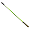
A fiber-optic temperature probe must be in contact with the material it is measuring. The more intimate the contact, the faster the crystal will respond to the temperature changes. A tiny crystal of GaAs with a dielectric mirror is bonded to one end of a cleaved optical fiber (see Figure 3). PTFE is then used to cover the entire assembly, serving as an excellent buffer.
At the opposite end of the probe is a stainless steel ST-type connector, through which white light is injected into the probe.
The light travels down the probe’s optical fiber, where some of it is absorbed by the GaAs crystal. The dielectric mirror reflects unabsorbed light, which returns down the probe to the coupler and is directed to a spectrometer (see Figure 4).
The position of the absorption shift is then analyzed and correlated back to temperature. Computation of the absorption shift does not depend on signal intensity; essentially, only the reflected light signature is of interest. Therefore, the various factors that contribute to attenuation on optical fibers (e.g., fiber length, number and quantity of connections, fiber diameter and composition, bending) do not impose any serious constraints. Furthermore, since the GaAs crystal’s response is universal and constant, no probe calibration is required.
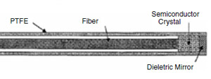
The fiber-optic temperature sensor probe consists of a gallium arsenide crystal and a dielectric mirror on one end of an optical fiber and a stainless steel connector at the other end. The entire assembly is coated with PTFE as a buffer.
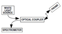
A white light source injects light into one of the branches of the coupler. This light travels down the probe's optical fiber to the gallium arsenide, which absorbs some of it. Unabsorbed light is reflected by the dieletric mirror and returned down the probe to the coupler, where it is directed to a spectrometer.


 Omega's relationship with Rutgers sprouted with their goals in substituting manual processes with an IoT solution for hands-off data collection capabilities.
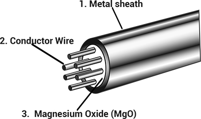 MI cables are used in high temperature or high pressure harsh environments for a good reason, here's why: