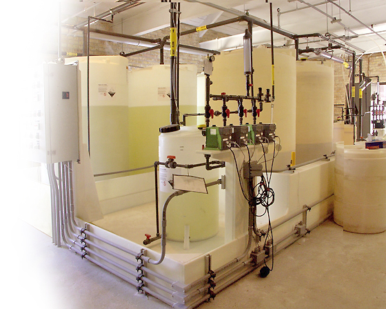
Chemical feed systems inject precise amounts of chemicals into processes to produce water fit for a specific purpose, maintain process efficiency, protect equipment and minimize costs. Chemical feed is separated into three main application segments including cooling, boiler and water treatment. Each requires a chemical feed system that basically includes a metering pump, storage tank and level sensor. Chemical feed tanks are small and often stand alone. They’re typically plastic mini-bulk tanks around 6’ in height, or IBC totes between 3’-6’ in height, or drums or pails that are 3’ or less in height. While purification requirements and processes differ in industrial, municipal and commercial applications, chemical feed plays a common role in water treatment. The primary requirement for this application is to monitor the liquid level and notify the operator when additional chemical supply is needed prior to running out, thus maintaining water integrity. Mini-bulk tanks are typically refilled from tanker trucks, while IBC totes, drums or pails are exchanged.
Technology
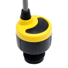
A short duration, high frequency ultrasonic sound wave is pulsed up to four times per second from the face of the transducer. The sound wave reflects off the surface of the liquid and returns to the transducer. The level sensor measures the time of flight between the sound generation and receipt, and translates this into the distance between the transducer face and liquid surface. The distance is then converted into a percentage of measured span and output as a proportional 4-20 mA signal.
Best Practices
The installed level sensor must have a clear view of the liquid surface. This means that the measurement space beneath the level sensor should be free of any obstructions such as pipes, fittings or walls inside the tank. The level sensor must be located above the highest liquid level and never be submersed during normal operation. Water treatment systems may be located indoors or outdoors. If outdoors, the chemical feed tanks likely have no environmental protection, and will be directly influenced by heat from the sun or cold from the weather. Where so, temperature differentials may generate condensation within the tank. This more often occurs at the high end of the temperature range, but may also occur at the low end, resulting in the formation of water droplets or ice on the transducer, which can affect acoustic transmission and receipt. Where significant condensation exists, select a level sensor with a longer more powerful measurement range, and apply a very thin layer of Rain-X or petroleum jelly water repellant across the transducer face. Liquid is normally dispensed into chemical feed tanks from the top and removed from the bottom. This typically creates an agitated liquid surface during filling and a smooth liquid surface during emptying. Depending upon the liquid type and amount of agitation, foam may be generated. Foam absorbs the acoustic signal and can reduce the effective measurement range of the level sensor. Where foam exists, the level sensor should be installed in a stand-pipe to separate out the surface foam from the point of measurement. Another solution is to extend the fill pipe to the bottom of the tank and eliminate the agitation. Vapor is normally associated with corrosive liquids in higher concentrations, but may also be found in non-corrosive liquids at higher temperatures. Vapor absorbs the acoustic signal and can reduce the effective measurement range of the level sensor. Where significant vapor exists, select a level sensor with a longer more powerful measurement range, and properly vent the tank. With strong vaporous acids such as hydrochloric or nitric, the level sensor should also be installed in a stand-pipe to maximize the acoustic signal strength.
Installation
There are several ways to mount a level sensor in this application. The inside of a chemical feed tank normally has few obstructions or equipment. The tank top may be flat, domed, round or angled. Find a mounting location where the level sensor has a direct view of the liquid throughout the entire measurement span. The location must be flat, level to the liquid and accessible. The following equipment can be used to install the sensor.
Coupling
A shorter half coupling is preferred over a taller full coupling. Use a coupling that is slip x thread, and avoid thread x thread couplings. If you use a full coupling, it must follow the height and diameter restrictions described under Riser with Flange.
Stand-Pipe
Level sensors can be installed in a stand-pipe to separate surface foam, dampen turbulence or maximize the acoustic signal strength of the level sensor. Do not use a stand-pipe in applications with dirty, coating or scaling liquids that will leave material build-up on the inner pipe wall. The stand-pipe must be one continuous section of smooth pipe without any breaks or transitions. The pipe’s inner diameter must be equal to or greater than the level sensors beam width and larger diameter pipes are recommended. To install the level sensor, mount a low-profile threaded coupling on top of the pipe. Just under the coupling, and within the level sensors dead band, drill two quarter inch vent holes on opposing sides of the pipe. The pipe should extend to the bottom of the tank, or at least below the level sensor’s measurement span. Cut a 45º angle on the bottom of the pipe. Finally, the level should be maintained above the 45º cut, so there’s always liquid in the pipe.
Tank adapters are recommended where the tank’s mounting location is level and not on a slope. Use a tank adapter that is slip x thread, and avoid thread x thread adapters. Do not use tank adapters that are mounted upside down.
A shorter half coupling is preferred over a taller full coupling. Use a coupling that is slip x thread, and avoid thread x thread couplings. If you use a full coupling, it must follow the height and diameter restrictions described under Riser with Flange.
Chemical feed tanks may be located near large pumps, motors or variable frequency drives that can generate substantial EMI or RFI noise. Make sure that such devices are grounded to earth, and then ground the level sensor and associated electrical equipment to the same earth-ground as these devices. Some areas may be subject to frequent lightning strikes or have un-reliable power. Where so, proper surge protection and filtering is recommended.
Long, narrow risers, which in fiberglass tanks may also extend a few inches inside the tank top, can affect acoustic transmission and receipt. The inner surface of the riser must be smooth and free of ridges, especially in the region below the installed transducer face. Risers with diameters of 3” or more are recommended. If the only option is a 2” diameter riser, the height of the riser and any mounting connections above it cannot exceed 5”. Caution should be taken with any riser heights greater than 8”, and the use of tee connections within the riser structure is not permissible.
Where possible, avoid installing the level sensor in the center of a dome top tank. The dome top acts like a parabolic reflector that amplifies acoustic energy and may cause the level sensor to perform intermittently at certain tank levels.
The level sensor outputs a 4-20 mA current signal that’s proportionate to the measurement span within the chemical feed tank. Users typically set the 4 mA to empty or the lowest measured level, and 20 mA to full or the highest measured level. Avoid placing the 4mA or 20mA span set points at or near levels where pumps, valves or alarms may actuate.
The level sensors 4-20 mA current signal is normally connected to a local controller or centralized control system. These devices may include a PLC, SCADA, DSC or stand-alone level controller. Either control device is fine as long as it accepts a 4-20 mA current signal. The operational range of the controller must then be programmed to match the measurement span of the level sensor, and take into account that the sensors 4 mA set point is normally placed above the empty tank condition. Once the controllers operational range has been configured to the correct levels and engineering units, then the relay set points are applied for pump, valve or alarm automation. Remember, the primary control requirement for this application is to notify the operator when additional chemical supply is needed, so they or their supplier can replenish the tank through refill or exchange prior to running out. This is normally done with a low level alarm for replenishment and a low-low level shut off for pump protection. Where tanks are refilled, an independent high level alarm or safety shut off system should always be used in addition to the primary system.
This material has been republished with permission from Flowline, Inc.
 CLOSE
CLOSE
 Ultrapure or high purity water has been purified to tight specifications to...
 Ultrasonic flow meters are non-intrusive devices that use acoustic vibrations to measure the flow rate of liquid...
 Indoor air quality is the responsibility of building owners, managers and employers.