Principles of Infrared Thermocouples
Introduction
IRt/c Infrared Thermocouples — A Revolutionary New Temperature Sensing Technology
The IRt/c product line represents a dramatic breakthrough in temperature sensing technology. The IRt/c sensors are unpowered, low cost, and can measure surface temperatures of materials without touching. They can be directly installed on conventional thermocouple controllers, PLCs, transmitters, and other readout devices.
How do they measure temperature?
All IRt/c's have a proprietary infrared detection system which receives the heat energy radiated from objects the sensor is aimed at, and converts the heat passively to an electrical potential. A millivolt signal is produced, which is scaled to the desired thermocouple characteristics.
Since all IRt/c's are self-powered devices, and rely only on the incoming infrared radiation to produce the signal through thermoelectric effects, the signal will follow the rules of radiation thermal physics, and be subject to the non-linearities inherent in the process.
However, over a range of temperatures, the IRt/c output is sufficiently linear to produce a signal which can be interchanged directly for a conventional t/c signal. For example, specifying a 2% match to t/c linearity results in a temperature range in which the IRt/c will produce a signal within 2% of the conventional t/c operating over that range. Specifying 5% will produce a somewhat wider range, etc.
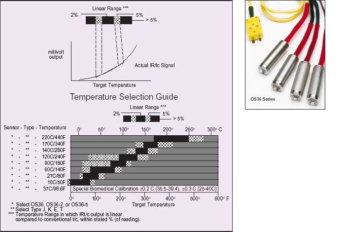
Each IRt/c model is specifically designed for optimum performance in the region of best linear fit with conventional t/c's, but can be used outside of those ranges by simply calibrating the readout device appropriately. The output signal is smooth and continuous over its entire rated temperature range, and maintains 1% repeatability over its entire range.
The Temperature Selection Guide is a summary of the linear range performance of each IRt/c model. The user selects the IRt/c model and type, and the target temperature range for the application. The normal offset adjustments on the thermocouple readout device are used to calibrate the installation for emissivity and background effects.
How reliable are these new devices?
Of fundamental interest in temperature control is the ability of the measuring device to maintain its calibration under service conditions, and over a long period of time. The IRt/c is rated at 1% (of reading) repeatability and to have no measurable long term calibration change, which makes it well suited for reliable temperature control. These attributes are inherent in the basic design and construction of each IRt/c.
Repeatability is defined as the ability of a measuring device to reproduce its calibration under identical conditions. The IRt/c is a solid, hermetically sealed, fully potted system that does not change either mechanically or metallurgically during service. There are no active electronic components and no power source to produce the signal - only the thermoelectric effects that produce a thermocouple signal. The 1% rating is a conservative value based on the practical difficulty of demonstrating tighter tolerances under test conditions, rather than a true limitation of the device.
Long term accuracy is influenced by the same things that influence repeatability: mechanical changes and metallurgical changes. It is well known that thermocouples can change calibration over time due to these effects. Mechanical changes occur because conventional thermocouples are constructed generally as small and light as possible to enhance response time, thus making them vulnerable to deformations that can change the thermoelectric properties. More importantly, the conventional thermocouple must operate at elevated temperature since it merely measures its own temperature.
The metallurgical changes which affect thermoelectric properties are a strong function of temperature, being negligible at room temperature, and of serious concern at high temperature.
 The IRt/c solves both problems by its design and basic operation. Its solid fully potted construction in a mechanically rigid stainless steel housing, and operation at near room temperature conditions, essentially eliminates the classical drift problems of conventional thermocouples. Every IRt/c is double annealed at temperatures above 100° C to ensure long term stability, and tested 5 times prior to packaging. Barring a very small percentage of failure, the IRt/c has essentially unlimited long term calibration accuracy.
Quick Installation Guide
All infrared-based sensing systems must be calibrated for specific material surface properties (for example, the amount of heat radiated from the target surface, environmental heat reflections, etc.). This calibration is performed by measuring the target surface temperature with a reliable independent surface temperature probe. The easiest and fastest method of accurately calibrating out these effects is to use an OMEGA OS91 hand-held Infrared Thermometer with a patented Automatic Emissivity Compensation System to give a true reading regardless of emissivity.
The following procedure is recommended:
- Install IRt/c as close as practical to view the target material to be measured.
- Wire IRt/c to controller, PLC Transmitter, etc. in standard fashion (including shield). As in conventional t/c's, red wire is always (-).
- Bring process up to normal operating temperature and measure actual temperature of target material with OS90 Series Infrared Thermometer.
- Adjust "input offset," "zero," "low cal," on the readout device to match the OS91 reading.
Installation complete.
IRt/c Setup With Auto-tune Temperature Controllers
In many applications, heating elements are employed to heat a product in an oven, furnace, or with jets of hot air. Conventional control devices using contact thermocouples measure and control the oven air temperature, IR heating element temperature, or air jet temperature in an effort to maintain product temperature and therefore, quality; often with less than satisfactory results.
Replacing the contact thermocouple, (for example measuring oven temperature) with a non-contact IRt/c measuring product temperature directly, will insure that product temperature is maintained. Some readjustment of the controller parameters is required because of differences in sensor response times (an IRt/c is much faster), and time required to heat the product compared to the original sensor (slower). After installing the IRt/c and calibrating the controller reading using an OS91 Infrared Scanner (see Quick Installation Guide below), initiate the self-tuning cycle of the controller and check to see that the control is stable and accurate. If it will not self tune properly, manually adjust the control coefficients to achieve stable control. Because the product temperature is likely to change temperature more slowly than the original sensor, start with slowly increasing the "D" of the PID coefficients.
IRt/c can be used with up to 1,000 ft (300 M) of thermocouple extension wire.
With twisted shielded pair thermocouple extension wire, an IRt/c can be mounted as far as 300 meters (1,000 ft) from the readout device, even in a very fierce electrical noise environment. A demonstration test was performed with a 300 m (1000 ft) coil of twisted shielded pair of extension wire, with 30 m (100 ft) unwound, connecting an IRt/c to a fast (100 msec. response) A/D conversion module to a computer. As a noise generator, a 60 Hz 10,000 volt transformer and spark generator was set up to spark within 15 cm (6 inches) of the wire.
The test results showed less than 0.1°C of noise at any relative position of the wire, spark, and transformer. The extraordinary noise suppression characteristics designed into the IRt/c make it possible to locate it at very long distances, without the necessity of a transmitter. The IRt/c housing is electrically isolated from the signal leads and is connected to the shielded ground of the extension cable. For long distances, twisted shielded extension cable should be used, and the shield connected to a good electrical ground.
IRt/c's are intrinsically safe when used with barriers.
"Field Apparatus having energy storing or generating characteristics of <1.2V, 0.1A, 25 mW or 25 microJ shall be considered Simple Apparatus (nonenergy storing). These general purpose devices may be used in a hazardous (classified) location without further approval when connected to a certified intrinsically safe circuit." - Quote from R. Stahl, Inc. Comprehensive Product Manual On Intrinsic Safety Barrier and Repeater Relays. Examples of non-energy storing Intrinsically Safe Apparatus are:
- Thermocouples
- RTD's
- LED's
- Dry Switch Contacts
- NAMUR Inductive Proximity Switches
- Non-inductive Strain Gage Devices and Resistors
The IRt/c falls into the category of thermocouples, since it generates its signal by converting the radiated heat energy to an electrical signal via Seebeck effects, the basic driving force of thermocouples. Like all thermocouples, it requires no power source and generates signals measured in millivolts of voltage, microamps of current and nanowatts of power. IRt/c's have a small capacitance, but at one microFarad, the energy storage is measured in nanojoules and is a thousand times lower than the 25 microjoule criterion.
Accordingly, the IRt/c qualifies as a Simple Apparatus for use in hazardous locations, and with the appropriate barrier, qualifies as Intrinsically Safe.
IRt/c's are intrinsically safe when used with barriers
IRt/c Application Notes
IRt/c monitors tire temperature for racing performance.
Tire temperature is of critical concern in automotive racing for two reasons: the tire temperature directly affects its adhesion and its wear characteristics; and tire temperature patterns provide valuable information on the set-up and performance of the suspension. For example, excessive loading of a tire caused by out-of-tune suspension will cause that tire to become considerably warmer than the others.
The IRt/c is an ideal measuring device for on-board data acquisition, due to its small size, ruggedness, and low cost. It may be connected to standard thermocouple read-out systems. Installation should include connecting the shield to a suitable ground in order to avoid interference from the electrically harsh environment of a racing automobile. Mechanical installation should include attention to air flow patterns to minimize dirt building on the lens. The OS36-2 or OS36-5 are recommended due to their narrower field of view, thus allowing you to position it further away.
IRt/c Relative humidity measurement.
IRt/c's can be used to measure actual relative humidity in many situations where there is a convenient source of water and flowing air, and measure it accurately and reliably.
An IRt/c aimed at a wet porous surface with ambient air blowing across the wet surface, can actually measure what is called "wet bulb" temperature for that ambient area. (More precisely, wet bulb temperature is the equilibrium temperature of the air-water interface when a water film is evaporated. When air is moved over a wet surface, the water cools by evaporation until it reaches wet-bulb temperature, then the cooling stops, no matter how much more air is moved over the surface. The temperature at which the cooling stops is the wet bulb temperature.)
The IRt/c measures the temperature of the air-water interface on a surface directly. The quality of the water or of the absorbing material does not affect the reading, since the IRt/c can directly view the air-water interface, and the wet bulb equilibrium temperature is not materially affected by impurities.
The highest precision method is to employ an IRt/c wired differentially with a conventional thermocouple to measure the quantity "wet bulb depression". The differential pair arrangement guarantees high accuracy, since RH is a strong function of wet bulb depression and a weak function of dry bulb temperature. Standard psychrometric tables, charts, and software algorithms can be used with the data to obtain accurate relative humidity for your environmental measurements.
Controlling Web Roller Temperature
The IRt/c infrared thermocouples have quickly become the sensors of choice for monitoring and controlling both web and roller temperatures. Tips on accurate roller temperature measurement:
1. Uncoated Metal or Chrome Rolls - Shiny, uncoated metal rolls are difficult for any infrared sensor to properly sense the true temperature (the sensor will see too many environmental reflections). The solution to the problem is to simply: paint a small black stripe on an unused end of the roller. Aim the IRt/c sensor at the black paint stripe. It will then measure the temperature accurately and reliably regardless of changes in the surface conditions of the rest of the roller.
If there is very little space on the edge of the roller, move the sensor closer and paint a very small black stripe. The minimum spot size of the IRt/c is 8 mm (0.3 inches) and for the OS36-2 it is 4 mm (0.16 inches) when the sensor is brought close to the surface.
2. Dull Metal Rollers - Dull metal rollers can provide a reliable signal. It is best to test the surface for reliability, though, as the surface emissive properties may shift via dirt, moisture, cleaning, etc. It is best, if in doubt, to simply paint a stripe to eliminate these variations.
3. Non-metallic Surfaced Rollers - These will provide a reliable IR signal at any point the IRt/c is aimed. No painted stripe is required.
Controlling Vacuum Forming and Thermoforming Processes
For forming plastics, an excellent combination of heating method and control is radiant heat with an IRt/c for control. They work extraordinarily well together, since both the heating and measuring occur right at the surface - where the plastic is located. The IRt/c reading is unaffected by reflections from the heater, since the spectral response of the 6-14 micron IRt/c lens filters out the shorter wavelengths of the radiant heater energy.
The IRt/c may be mounted in between ceramic heaters, or in the shroud or reflector of the radiant heater, such that it can see in between the elements. Select the IRt/c standard, OS36-2 or OS36-5 model, depending on the field-of-view required to see past the elements to the painted surface. Care should be taken in mounting the IRt/c in such a way as to keep its temperature below 93°C (200°F) and to keep the lens clean. The OS36-2 is the preferred model for this application because of its small physical size with built-in air purge. It can be used in temperatures to 121°C (250°F) environments when the air purge system is used. Its narrower field-of-view allows more leeway in positioning, and thus more flexibility in installation. For still narrower fields of view, use the OS36-5 with its 5:1 FOV.
IRt/c Controls Printed Circuit Board Preheat During Wave Soldering
An excellent solution to the problem of proper heater control for PC board preheat is an IRt/c. They work extraordinarily well together, since both the heating and measuring occur right at the surface - where the solder must flow. The IRt/c reading is unaffected by reflections from the heater, since the spectral response of the 6-14 micron IRt/c lens filters out any shorter wavelengths of the radiant heater energy.
For this application, the IRt/c may be mounted identically to Vacuum Forming/Thermoforming (above).
Induction Heater Control
The induction heating process can be readily controlled by the temperature of the part as measured by an IRt/c non-contact infrared thermocouple. Several issues should be considered in an installation.
1. The effect of the field on the IRt/c: since the measuring signal is electrically isolated from the housing, the IRt/c will operate in even a very strong field. The shield wire should be attached to a proper signal ground. If there is excessive heating from the field, consider using the optional cooling jacket kit, with the same water source as is used to cool the coil.
2. The field-of-view: the preferred method is to view the part between the coil turns or from the end. Select the IRt/c model that best suits the requirements.
3. Part temperature: both the OS36-2 and OS36-5 models can be used to target temperatures of 1100°C (2000°F), and have linear ranges to 260°C (500°F).
Asphalt Temperature Monitoring
Asphalt properties are particularly sensitive to temperature, and it is important that the asphalt is applied at the correct temperature in order to perform to its specifications. Accordingly, temperature monitoring is a common requirement, but the thermocouples normally used have severe breakage problems due to the harsh abrasiveness of the material, and must constantly be replaced at high cost and interruption of production.
The IRt/c solves this problem directly, since the temperature is monitored without contact. The normal thermocouple controller can be used - simply calibrate offset if necessary. The OS36-2 and OS36-5 models are recommended due to their built-in air purge, which will keep the lens clean by preventing vapors from condensing on the lens. The OS36-2 can be mounted in the chute to view the asphalt through a small hole, while the OS36-5 can be mounted some distance away due to its narrow 5:1 field of view.
Reproduced with permission of Exergen Corp.
Printable Version
 CLOSE
CLOSE