RTD elements and sensors
Introduction to resistance thermomethers and sensor
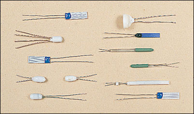 RTD elements come in many types conforming to different standards, capable of different temperature ranges, with various sizes and accuracies available. But they all function in the same manner: each has a pre-specified resistance value at a known temperature which changes in a predictable fashion. In this way, by measuring the resistance of the element, the temperature of the element can be determined from tables, calculations or instrumentation. These resistance elements are the heart of the RTD (Resistance Temperature Detector). Generally, a bare resistance element is too fragile and sensitive to be used in its raw form, so it must be protected by incorporating it into an RTD.
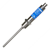
Resistance Temperature Detector is a general term for any device that senses temperature by measuring the change in resistance of a material. RTD’s come in many forms, but usually appear in sheathed form. An RTD probe is an assembly composed of a resistance element, a sheath, lead wire and a termination or connection. The sheath, a closed end tube, immobilizes the element, protecting it against moisture and the environment to be measured. The sheath also provides protection and stability to the transition lead wires from the fragile element wires.
Some RTD probes can be combined with thermowells for additional protection. In this type of application, the thermowell may not only add protection to the RTD, but will also seal whatever system the RTD is to measure (a tank or boiler for instance) from actual contact with the RTD. This becomes a great aid in replacing the RTD without draining the vessel or system.
Thermocouples are the old tried and true method of electrical temperature measurement. They function very differently from RTD’s but generally appear in the same configuration: often sheathed and possibly in a thermowell. Basically, they operate on the Seebeck effect, which results in a change in thermoelectric emf induced by a change in temperature. Many applications lend themselves to either RTD’s or thermocouples. Thermocouples tend to be more rugged, free of self-heating errors and they command a large assortment of instrumentation. However, RTD’s, especially platinum RTD’s, are more stable and accurate.
History
The same year that Seebeck made his discovery about thermoelectricity, Sir Humphrey Davy announced that the resistivity of metals showed a marked temperature dependence. Fifty years later, Sir William Siemens proffered the use of platinum as the element in a resistance thermometer. His choice proved most propitious, as platinum is used to this day as the primary element in all high-accuracy resistance thermometers. In fact, the Platinum Resistance Temperature Detector, or RTD Pt100, is used today as an interpolation standard from the oxygen point (-182.96°C) to the antimony point (630.74°C).
Platinum is especially suited to this purpose, as it can withstand high temperatures while maintaining excellent stability. As a noble metal, it shows limited susceptibility to contamination.
The classical resistance temperature detector (RTD) construction using platinum was proposed by C.H. Meyers in 1932. He wound a helical coil of platinum on a crossed mica web and mounted the assembly inside a glass tube. This construction minimized strain on the wire while maximizing resistance.
 Although this construction produces a very stable element, the thermal contact between the platinum and the measured point is quite poor. This results in a slow thermal response time. The fragility of the structure limits its use today primarily to that of a laboratory standard.
Another laboratory standard has taken the place of Meyers’ design. This is the bird-cageelement proposed by Evans and Burns. The platinum element remains largely unsupported, which allows it to move freely when expanded or contracted by temperature variations.
Strain-induced resistance changes over time and temperature are thus minimized, and the bird-cage becomes the ultimate laboratory standard. Due to the unsupported structure and subsequent susceptibility to vibration, this configuration is still a bit too fragile for industrial environments.
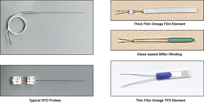
A more rugged construction technique is shown in Figure 37. The platinum wire is bifilar wound on a glass or ceramic bobbin. The bifilar winding reduces the effective enclosed area of the coil to minimize magnetic pickup and its related noise. Once the wire is wound onto the bobbin, the assembly is then sealed with a coating of molten glass. The sealing process assures that the RTD will maintain its integrity under extreme vibration, but it also limits the expansion of the platinum metal at high temperatures. Unless the coefficients of expansion of the platinum and the bobbin match perfectly, stress will be placed on the wire as the temperature changes, resulting in a strain-induced resistance change. This may result in a permanent change in the resistance of the wire.
There are partially supported versions of the RTD which offer a compromise between the bird-cage approach and the sealed helix. One such approach uses a platinum helix threaded through a ceramic cylinder and affixed via glass-frit. These devices will maintain excellent stability in moderately rugged vibrational applications.
TYPICAL RTD’s (FIgures 36 and 37)
Metal Film RTD’s
In the newest construction technique, a platinum or metal-glass slurry film is deposited or screened onto a small flat ceramic substrate, etched with a lasertrimming system, and sealed. The film RTD offers substantial reduction in assembly time and has the further advantage of increased resistance for a given size. Due to the manufacturing technology, the device size itself is small, which means it can respond quickly to step changes in temperature. Film RTD’s are presently less stable than their hand-made counterparts, but they are becoming more popular because of their decided advantages in size and production cost. These advantages should provide the impetus for future research needed to improve stability.
Metals - All metals produce a positive change in resistance for a positive change in temperature. This, of course, is the main function of an RTD sensor. As we shall soon see, system error is minimized when the nominal value of the RTD resistance is large. This implies a metal wire with a high resistivity. The lower the resistivity of the metal, the more material we will have to use.
The following table lists the resistivities of common materials for a resistance thermometer.
| METAL |
|
RESISTIVITY OHM/CMF
(cmf = circular mil foot) |
|
|
|
Gold
Silver
Copper
Platinum
Tungsten
Nickel |
Au
Ag
Cu
Pt
w
Ni |
|
|
13.00
8.8
9.26
59.00
30.00
36.00 |
|
Because of their lower resistivities, gold and silver are rarely used as RTD elements. Tungsten has a relatively high resistivity, but is reserved for very high temperature applications because it is extremely brittle and difficult to work.
Copper is used occasionally as an RTD element. Its low resistivity forces the element to be longer than a platinum element, but its linearity and very low cost make it an economical alternative. Its upper temperature limit is only about 120ºC.
The most common RTD’s are made of either platinum, nickel, or nickel alloys. The economical nickel derivative wires are used over a limited temperature range. They are quite non-linear and tend to drift with time. For measurement integrity, platinum is the obvious choice.
RTD Elements manufactures in Omega
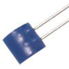 pt100 Elements
Thi surface element is a special type of pt100 element. It is designed to be as thin as possible thus providing good contact for temperature measurement of flat surfaces.
RTD Element Characteristics
There are several very important details that must be specified in order to properly identify the characteristics of the RTD element:
- Material of Resistance Element (Platinum, Nickel, etc.)
- Temperature Coefficient
- Nominal Resistance
- Temperature Range of Application>
- Physical Dimensions or Size Restrictions
- Accuracy
1. Material of Resistance Element
Several metals are quite common for use in resistance elements and the purity of the metal affects its characteristics. Platinum is by far the most popular due to its linearity with temperature. Other common materials are nickel and copper, although most of these are being replaced by platinum elements. Other metals used, though rarely, are Balco (an iron-nickel alloy), tungsten and iridium.
2.Temperature Coefficient
The temperature coefficient of an element is a physical and electrical property of the material. This is a term that describes the average resistance change per unit of temperature from ice point to the boiling point of water. Different organizations have adopted different temperature coefficients as their standard. In 1983, the IEC (International Electrotechnical Commission) adopted the DIN (Deutsche Institute for Normung) standard of Platinum 100 ohm at 0ºC with a temperature coefficient of 0.00385 ohms per ohm degree centigrade. This is now the accepted standard of the industry in most countries, although other units are widely used. A quick explanation of how the coefficient is derived is as follows: Resistance at the boiling point (100ºC) =138.50 ohms. Resistance at ice point (0ºC) = 100.00 ohms. Divide the difference (38.5) by 100 degrees and then divide by the 100 ohm nominal value of the element. The result is the mean temperature coefficient (alpha) of 0.00385 ohms per ohm per ºC.
Some of the less common materials and temperature coefficients are:
| Pt TC | = | .003902 (U.S. Industrial Standard) |
| Pt TC | = | .003920 (Old U.S. Standard) |
| Pt TC | = | .003923 (SAMA) |
| Pt TC | = | .003916 (JIS) |
| Copper TC | = | .0042 |
| Nickel TC | = | 0.00617 (DIN) |
| Nickel TC | = | .00672 (Growing Less Common in U.S.) |
| Balco TC | = | .0052 |
| Tungsten TC | = | 0.0045 |
Please note that the temperature coefficients are the average values between 0 and 100ºC. This is not to say that the resistance vs. temperature curves are truly linear over the specified temperature range.
 3. Nominal Resistance
Nominal Resistance is the prespecified resistance value at a given temperature. Most standards, including IEC-751, use 0ºC as their reference point. The IEC standard is 100 ohms at 0ºC, but other nominal resistances, such as 50, 200, 400, 500, 1000 and 2000 ohm, are available.
4.Temperature Range of Application
Depending on the mechanical configuration and manufacturing methods, RTD’s may be used from -270ºC to 850ºC. Specifications for temperature range will be different, for thin film, wire wound and glass encapsulated types, for example.
5. Physical Dimensions or Size Restrictions
The most critical dimension of the element is outside diameter (O.D.), because the element must often fit within a protective sheath. The film type elements have no O.D. dimension.To calculate an equivalent dimension, we need to find the diagonal of an end cross section (this will be the widest distance across the element as it is inserted into a sheath).
Permissible deviations fot PT100 table
| Class A |
Temperature
ºC | Deviation |
| ohms | ºC |
| -200 | ±0.24 | ±0.55 |
| -100 | ±0.14 | ±0.35 |
| 0 | ±0.06 | ±0.15 |
| 100 | ±0.13 | ±0.35 |
| 200 | ±0.20 | ±0.55 |
| 300 | ±0.27 | ±0.75 |
| 400 | ±0.33 | ±0.95 |
| 500 | ±0.38 | ±1.15 |
| 600 | ±0.43 | ±1.35 |
| 650 | ±0.46 | ±1.45 |
| |
| Class B |
Temperature
ºC | Deviation |
| ohms | ºC |
| -200 | ±056 | ±1.3 |
| -100 | ±0.32 | ±0.8 |
| 0 | ±0.12 | ±0.3 |
| 100 | ±0.30 | ±0.8 |
| 200 | ±0.48 | ±1.3 |
| 300 | ±0.64 | ±1.8 |
| 400 | ±0.79 | ±2.3 |
| 500 | ±0.93 | ±2.8 |
| 600 | ±1.06 | ±3.3 |
| 650 | ±1.13 | ±3.6 |
| 700 | ±1.17 | ±3.8 |
| 800 | ±1.28 | ±4.3 |
| 850 | ±1.34 | ±4.6 |
|
For example, using an RTD element that is 10 x 2 x 1.5 mm, the diagonal can be found by taking the square root of (22 + 1.52).Thus, the element will fit into a 2.5 mm (0.98") inside diameter hole. For practical purposes, remember that any element 2 mm wide or less will fit into a 1/8" O.D. sheath with 0.010" walls, generally speaking. Elements which are 1.5 mm wide will typically fit into a sheath with 0.084" bore. Refer to Figure 1.
6. Accuracy
IEC 751 specifications for Platinum Resistance Thermometers have adopted DIN 43760 requirements for accuracy. DIN-IEC Class A and Class B elements are shown in the chart on this page.
7. Response Time
50% Response is the time the resistance thermometer element needs in order to reach 50% of its steady state value. 90% Response is defined in a similar manner. These response times of elements are given for water flowing with 0. 2 m/s velocity and air flowing at 1 m/s.They can be calculated for any other medium with known values of thermal conductivity. In a 1/4" diameter sheath immersed in water flowing at 3 feet per second, response time to 63% of a step change in temperature is less than 5.0 seconds.
8. Measurement Current and Self Heating
Temperature measurement is carried out almost exclusively with direct current. Unavoidably, the measuring current generates heat in the RTD.The permissible measurement currents are determined by the location of the element, the medium which is to be measured, and the velocity of moving media. A self-heating factor, “S”, gives the measurement error for the element in ºC per milliwatt (mW). With a given value of measuring current, I, the milliwatt value P can be calculated from P = I2R, where R is the RTD’s resistance value. The temperature measurement error Δ T (ºC) can then be calculated from Δ T = P x S.
RTD Element Specifications
Stability: Better than 0.2ºC after 10,000 hours at maximum temperature (1 year, 51 days, 16 hours continuous).
Vibration Resistance: 50 g @ 500ºC; 200 g @ 20ºC; at frequencies from 20 to 1000 cps.
Temperature Shock Resistance: In forced air: over entire temperature range. In a water quench: from 200 to 20ºC.
Pressure Sensitivity: Less than 1.5 x 10⁻⁴ C/PSI, reversible.
Self Heating Errors & Response Times: Refer to specific Temperature Handbook pages for the type of element selected.
Self Inductance From Sensing Current: Can be considered negligible for thin film elements; typically less than 0.02 microhenry for wire wound elements.
Capacitance: For wire wound elements: calculated to be less than 6 PicoFarads; for film-type elements: capacitance is too small to be measured and is affected by lead wire connection. Lead connections with element may indicate about 300 pF capacitance.
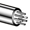
RTP probe with 2,3 or 4 wire configuration
 Beaded Wire Thermocouple
Omega Engineering manfactures any type of RTD probes and elements. 2, 3 or 4 wires RTD configuration probes are ready to be dispatched.
RTD and Pt100 Wiring Configurations
As stated previously, a Resistance Temperature Detector (RTD) element generally appears in a sheathed form. ON the other hand, the most popular RTD element is the Pt100. Obviously, all of the criteria applicable to resistance elements also apply here, but rather than element size, the construction and dimensions of the entire RTD assembly must be considered. Since the lead wire used between the resistance element and the measuring instrument has a resistance itself, we must also supply a means of compensating for this inaccuracy. Refer to Figure 2 for the 2-wire configuration.
The circle represents the resistance element boundaries to the point of calibration. 3- or 4-wire RTD configuration must be extended from the point of calibration so that all uncalibrated resistances are compensated.
The resistance RE is taken from the resistance element and is the value that will supply us with an accurate temperature measurement. Unfortunately, when we take our resistance measurement, the instrument will indicate RTOTAL:
Where
RT = R1 + R2 + RE
This will produce a temperature readout higher than that actually being measured. Many systems can be calibrated to eliminate this.
The common values of resistance for a platinum RTD range from 10 ohms for the bird-cage model to several thousand ohms for the film RTD. The single most common value is 100 ohms at 0ºC (RTD Pt100). The DIN 43760 standard temperature coefficient of platinum wire is α = .00385. For a 100 ohm wire, this corresponds to + 0.385 ohms/ºC at 0ºC. This value for α is actually the average slope from 0ºC to 100ºC. The more chemically pure platinum wire used in platinum resistance standards has an α of +.00392 ohms/ohm/ºC.
Both the slope and the absolute value are small numbers, especially when we consider the fact that the measurement wires leading to the sensor may be several ohms or even tens of ohms. A small lead impedance can contribute a significant error to our temperature measurement.
A ten ohm lead impedance implies 10/.385 ≈ 26ºC error in measurement. Even the temperature coefficient of the lead wire can contribute a measurable error. The classical method of avoiding this problem has been the use of a bridge.
The bridge output voltage is an indirect indication of the RTD resistance. The bridge requires four connection wires, an external source, and three resistors that have a zero temperature coefficient. To avoid subjecting the three bridge-completion resistors to the same temperature as the RTD sensor, the RTD is separated from the bridge by a pair of extension wires:
These extension wires recreate the problem that we had initially: The impedance of the extension wires affects the temperature reading. This effect can be minimized by using a three-wire bridge configuration:
If wires A and B are perfectly matched in length, their impedance effects will cancel because each is in an opposite leg of the bridge. The third wire, C, acts as a sense lead and carries no current.
The Wheatstone bridge shown in Figure 41 creates a non-linear relationship between resistance change and bridge output voltage change. This compounds the already non-linear temperature-resistance characteristic of the RTD by requiring an additional equation to convert bridge output voltage to equivalent RTD impedance.
This configuration provides one connection to one end and two to the other end of the sensor. Connected to an instrument designed to accept 3-wire RTD input, compensation is achieved for lead resistance and temperature change in lead resistance. This is the most commonly used configuration.
If three identical type wires are used and their lengths are equal, then R1 = R2 = R3. By measuring the resistance through leads 1, 2 and the resistance element, a total system resistance is measured (R1 + R2 + RE ). If the resistance is also measured through leads 2 and 3 (R2 + R3), we obtain the resistance of just the lead wires, and since all lead wire resistances are equal, subtracting this value (R2 + R3) from the total system resistance (R1 + R2 + RE) leaves us with just RE, and an accurate temperature measurement has been made. A 4-wire configuration is also used. (See Figure 4.) Two connections are provided to each end of the sensor. This construction is used for measurements of the highest precision.
With the 4-wire RTD configuration, the instrument will pass a constant current (I) through the outer leads, 1 and 4.
The voltage drop is measured across the inner leads, 2 and 3. So from V = IR we learn the resistance of the element alone, with no effect from the lead wire resistance. This offers an advantage over 3-wire RTD configurations only if dissimilar lead wires are used, and this is rarely the case.
4-Wire RTD - The technique of using a current source along with a remotely sensed digital voltmeter alleviates many problems associated with the bridge.
The output voltage read by the dvm is directly portional to RTD resistance, so only one conversion equation is necessary. The three bridge-completion resistors are replaced by one reference resistor. The digital voltmeter measures only the voltage dropped across the RTD and is insensitive to the length of the lead wires.
The one disadvantage of using 4-wire RTD probe is that we need one more extension wire than the 3-wire bridge. This is a small price to pay if we are at all concerned with the accuracy of the temperature measurement.
Still another configuration, now rare, is a standard 2-wire configuration with a closed loop of wire alongside (Figure 5). This functions the same as the 3-wire RTD configuration, but uses an extra wire to do so. A separate pair of wires is provided as a loop to provide compensation for lead resistance and ambient changes in lead resistance.
3-Wire Bridge Measurement Errors
If we know VS and VO, we can find Rg and then solve for temperature. The unbalance voltage Vo of a bridge built with R1 = R2 is:
If Rg = R3, VO= 0 and the bridge is balanced. This can be done manually, but if we don’t want to do a manual bridge balance, we can just solve for Rg in terms of VO:
This expression assumes the lead resistance is zero. If Rg is located some distance from the bridge in a 3-wire configuration, the lead resistance RL will appear in series with both Rg and R3:
Again we solve for Rg:
The error term will be small if Vo is small, i.e., the bridge is close to balance. This circuit works well with devices like strain gauges, which change resistance value by only a few percent, but an RTD changes resistance dramatically with temperature. Assume the RTD resistance is 200 ohms and the bridge is designed for 100 ohms:
Since we don’t know the value of RL, we must use equation (a), so we get:
The correct answer is of course 200 ohms. That’s a temperature error of about 2.5ºC.
Unless you can actually measure the resistance of RL or balance the bridge, the basic 3-wire technique is not an accurate method for measuring absolute temperature with an RTD. A better approach is to use a 4-wire technique.
Resistance to Temperature Conversion
The RTD is a more linear device than the thermocouple, but it still requires curve-fitting. The Callendar-Van Dusen equation has been used for years to approximate the RTD curve:
Where:
| RT | = | Resistance at Temperature T |
| Ro | = | Resistance at T = 0ºC |
| α | = | Temperature coefficient at T = 0ºC ((typically +0.00392Ω/Ω/ºC)) |
| δ | = | 1.49 (typical value for .00392 platinum) |
| β | = | 0 T > 0
0. 11 (typical) T < 0 |
The exact values for coefficients α , β, and δ are determined by testing the RTD at four temperatures and solving the resultant equations. This familiar equation was replaced in 1968 by a 20th order polynomial in order to provide a more accurate curve fit. The plot of this equation shows the RTD to be a more linear device than the thermocouple.
 CLOSE
CLOSE