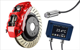
Measuring Brake System Temperature with Infrared Sensors
Brake systems are perhaps the most crucial component of any moving machine. Brake system problems can lead to accidents and must be avoided at all costs.
Even a small dip in brake performance can have serious consequences. If brakes overheat, for example, system efficiency will dip. This can potentially cause a fire. It is therefore vital to stress-test brakes during product R&D. This usually involves measuring and monitoring brake temperature at the limits of performance.
In this article, we will look at how to test brake systems using the most suitable method available: infra-red (IR) measurement. We will also discuss field of view, focal length, and the complications of calibrating an IR sensor.
Why infrared sensors?
Brakes are usually spinning fast when we want to measure their temperature. A normal surface-contact sensor, like a thermocouple, will not work as its wires are likely to become tangled.
A wireless transmitter cannot solve the problem either. Because brakes spin and vibrate so quickly, they affect the performance of the electronics inside wireless transmitters.
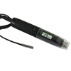
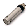
The best solution is therefore to use infra-red sensors.
Understanding field of view
Measuring brake temperature is not as simple as pointing an IR sensor at the system from any distance or angle. ‘Field of view’ must also be considered.
The field of view of an infra-red sensor defines the size of the measurement target at a specified distance from the sensor. It can be shown in a diagram or a table such as the one below.
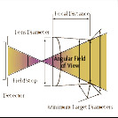
Each type of IR sensor has a specific field of view, such as 10:1, 20:1 or 40:1. These numbers show the ratio between:
- the distance of the sensor from the measurement target (the number on the left); and
- the target spot size (the number on the right).
For example, a 20:1 IR positioned 200cm from a brake can ‘see’ a target spot of diameter 10cm. At 300cm away, the spot size would be 15cm. This is the sensor’s field of view.
An infrared sensor calculates the average temperature of the spot in its field of view. The sensor must be ‘on target’, or the reading will not be accurate.
Focusing field of view
Field of view can also be calibrated for specialised measurements, as in the two examples below.
- Average temperature of whole brake: When measuring the average temperature of the whole brake, it is important to give the IR sensor the biggest possible field of view without exceeding the boundary of the brake. With a 30cm-diameter brake and 10:1 IR sensor, the sensor is best positioned 300cm away.
- Measuring specific part of brake: If the goal is to measure a specific 1cm point on the same brake with the same IR sensor, e.g. for temperature profiling, it is best to position the sensor 10cm away and point it at the desired spot.
As we can see, IR sensor field of view provides control over the size and position of the measurement spot. The viewing angle also affects the target size and shape.
Understanding focal length
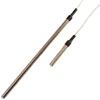
Another important specification is focal length, which is the distance from a measurement target an IR sensor is effective at.
Close-focus IR sensors have working ranges of around 0.2cm to 150cm, while long-range sensors can work at up to 1.5 metres away.
In practical terms, one cannot simply move an IR sensor further and further back to increase its field of view infinitely. Placement must take the sensor’s focal length into account.
Magnifying with telescopic eyepieces:Some IR sensors also feature telescopic eyepieces, which allow for measurement of smaller targets at greater distances. At close range, optical systems can measure spots as tiny as 0.03 inches. Small targets can also be measured at longer range; for example, a 3-inch target could be measured from 30 feet.
Spherical and chromatic aberration
Any statement of field of view is an approximation because of fuzziness caused by spherical and chromatic aberration.
Spherical aberration is what happens when rays that hit the lens far away from its axis are bent more than rays passing the lens near its axis.
Chromatic aberration happens because the refractive index of optical materials changes with wavelength. The refractive index is lower at shorter wavelengths. Shorter-wavelength rays are therefore bent more, and focus nearer the lens. Longer-wavelength rays are focused farther from the lens.
Every field of view is therefore affected by fuzziness. Some IR sensor manufacturers include the effects of aberrations in field of view statements.
Choosing a sensor
Omega Engineering offers a comprehensive range of infrared temperature sensors.
The OS-MINI Series can handle temperatures from -20° to 1,020°C, with fields of view from 2:1 to 30:1. Models also offer optional touchscreen controls, Micro SD data logging, and the ability to withstand up to 180°C without cooling.
Read more about
OS-MINI Series IR temperature sensors
If you would like to know more or discuss your brake system temperature measurement needs with our technical team,
contact us today.
temperature probe | Related Products
 CLOSE
CLOSE