 CLOSE
CLOSE
Load cell mounting design
 Each load cell installation is unique; consult a structural engineer when in need of very high accuracy, long-term stability, custom applications and specifications, and when using varied R&D environments. In order to gain precise weighing results, be sure to use specified load applications for load cells.
Load cells have a specified load direction, do not apply side forces, bending or torsional movements on load cells. Inappropriate loading applications will risk reducing the life of load cells, plus distortion of correct measurement results.
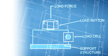
A rigid load cell mounting design for the support structure of load cells in compressive loading applications is preferred to pliable designs to achieve even lowering of all supports that also distributes tension, and provides an even contact surface.
Mounting the load cells to the support structure and rigid base plate, ensures even load transfer from the base of the load cell to the support structure. This structure must also have the capacity to support the forces corresponding with the load. Installing aids may be needed for compliance with load cell installation. Seek assistance from the design engineer to determine the weighting of individual disturbance possibilities. Special considerations for weighing tanks, thermal expansions, monitoring levels, and horizontal movements for certain tank shapes and support structures are required to avoid measurement distortions. Your load cell mointing design may need end-stops to limit lateral deflection, and elastomeric bearings can also regulate heat between the tank and load cell. Also if your load cell requires self-centering, the design engineer may suggest a pendulum load cell that will automatically guide the super structure into its original position.
After the installation, the load cell system would need to be calibrated.
Specific Applications
Gas Turbine Engine/Rocket: High accuracy measurements of the volumetric flow of gas through the pipeline. The turbine rotor turns the rotor blades by gas flow into the meter, measuring gas velocity. The rotor blades pass a pickup coil, generating an electrical signal pulse. The pulse is equal to a specific volume of gas. Total volumetric flow is recorded by the number of pulses. Expression of flow rate is measured in actual cubic feet or actual cubic meters, (ACF/AM3).
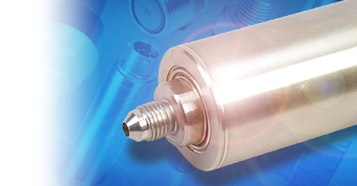
Engine Thrust Measurement: This built-to-order combination torque and thrust reactionary and rotary load cell product is constructed in all stainless steel for long term reliability. Applications in industrial environments include safe overload of 150% of capacity, ultimate overload at 300% of capacity. Call engineering for specifics.
Bin Weighing: To simplify load cell installations, use tank and bin weighing systems with capacities of up to 2500 pounds. Systems provide shock absorption for industrial load cells installations and helps to prevent improper mounting, which can cause load cell damage. Make a complete four point system with 4000 pound maximum capacity with heavy duty shear beam type load cells and tank and bin weighing system.
Process Control Systems: The wide range of process controllers include temperature controllers, ramp and soak controllers, dual-zone controllers, and bench-top style process controllers. Microprocessor based controllers come with various displays, wire RTDs, process voltage and current. They can connect directly to the Ethernet network featuring an embedded web server, downloadable data acquisition software.
High Load Fatigue Testing: Reduces time needed for troubleshooting scale systems, analyzes conditions of strain gage-based load cells in scale and industrial applications. Test load cells without disconnection, easy-to-read, clear screen messages. Provides essential data, like possible distortions from overloads, metals fatigue or shock loading, and possible ground faults or bridge resistance electrical problems.
Bridge Testing: Using a terminal block system with bridging and testing accessories across different clamping technologies reduces inventory and logistics costs. A modular terminal block design can be combined with different terminal block types or individually for application flexibility.
Considerations before installation
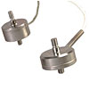
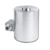
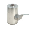
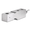
Types of load cell mountings: In addition to typical installations of hydraulic, pneumatic, and strain gage types of load cells, OMEGA customers often ask about bending beam load cells, shear beams, canister type, ring and pancake load cells, and button and washer type load cell mounting. Some other more advanced types of load cell installations for specific uses include helical, fiber optic, and piezo-resistive types of load cell mountings. Contact Omega for details on your specific load sensor installation requirements.
Load Orientation: Service technicians find the most common cause of accuracy problems with load measurements are incorrect load cell mounting which results in imprecise vertical loading that creates extraneous force errors. The loads must act precisely in the direction of the load cell.
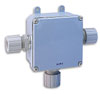
Environment: Magnetic and electrical fields can sometimes create interference voltage within a measuring circuit. To ensure protection from EMC, place the load cell, connection cabling, and electronics in a shielded housing. Do not ground the indicator, amplifier, and transducer more than once.
Framework of Structure: Protect the measurement cable using steel conduits. Use shielded, low-capacity measurement cables such as HBM cables. Avoid stray fields from motors, contact switches, and transformers. Using a rigid design for the support structure of load cells in compressive loading applications, preferred to pliable designs, to achieve even/balanced lowering of all supports that also distribute tension, and providing an even contact surface. Mounting load cells to the support structure, and rigid base plate ensures even load transfer from the base of the load cell to the support structure. This structure must also have the capacity to support the forces corresponding with the load.
Today’s mechanical scales can weigh loads of all kinds, from pharmaceuticals to tanks and shipping cars. The consistency of weight calculations and readings require the best weight balancing mechanism designs engineered to sense force, proper calibration, and maintenance. Depending on the output signals generated, we distinguish load cell designs according to weight detection, such as tension, compression, bending or shear, for example. Strain gage load cells convert on acting loads into electrical signals. The change in pressure of internal filling fluid measures weight using force balancing devices in hydraulic load cell designs. Higher accuracy requirements can be achieved using multiple dampener chambers which also operate on the force balance concept with pneumatic load cell engineering.
Wiring a Load Cell
One of the most common applications is acquiring data from a load cell or any full-bridge type sensor such as a strain gauge bridge with an A/D board. It is also the least understood, and many users make simple wiring errors, causing excessive noise, and in extreme cases, damage to the sensor and instrument.
The first thing to remember when using a load cell is that you must measure it with a DIFFERENTIAL input type, and not a SINGLE ENDED input type.
First, determine if your A/D device (your PLC, meter or DAS) can be configured as a differential input. Then, you must use a regulated power supply to provide excitation for your sensor.
If the power supply is noisy, or unregulated, then the sensor output will also be noisy or will drift. Some A/D boards have built in regulated power supplies, however, you may not be able to connect more that one or two sensors due to current limitations.
Plug-in boards usually provide a +5V and -5V connection, however, this is usually the computer's PC power supply which is not suitable for bridge sensor excitation.
The best thing to do is to purchase a separate highly regulated power supply like this one that can handle the current for all of the sensors that need to be powered.
The following diagram will demonstrate the correct wiring configuration for a load cell to a differential input. Keep in mind that if more than one laod sensor is connected to the same power supply, you only need to connect the ground screw to only ONE ground, otherwise, a ground loop may be created causing additional noise.
Also, make sure that the power supply is FLOATING, meaning that it is not already connected to another ground anywhere else.

 In the airline industry weight is money. Every additional pound requires more fuel to lift...
 How to use strain gauges and optimize their performance while working with inhomogeneous materials
 Understand the necessary criteria to select the right type of pressure transducer for your application