 CLOSE
CLOSE
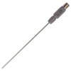
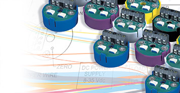 Temperature transmitters are used to send a signal from a temperature sensor, such as a thermocouple or RTD, to a measurement or control device. The temperature transmitter amplifies and conditions the signal produced by the sensor before relaying it to the recording device. Temperature transmitters can reduce noise from RFI and EMI that may interfere with signals produced by temperature sensors and improve the accuracy of measurements. While DCS and PLC systems record measurements over the entire range of the sensor, a temperature transmitter can be calibrated to any specific range within its capabilities. Restricting measurements to a narrow range improves accuracy.
 Thermocouple Transmitter Calibration
Equipment needed for calibration of the thermocouple transmitter includes:
- Precision mV source with mV accuracy of ±0.002 and mV resolution of 0.001 or
- Precision DVM with mV accuracy of ±0.002 mV and an adjustable mV source with mV resolution of 0.001
- A stable ice bath
- Reference thermocouple
- Precision DMM with mA accuracy of ±0.002 and mA resolution of 0.001
Prepare the ice bath by filling a glass beaker with crushed ice made from distilled water and adding enough distilled water to create slush. Do not add enough water for the ice to float. Insert the reference thermocouple. Alternatively, a thermocouple calibrator can be used in place of the DVM, ice bath and voltage source. For calibration using the ice bath, connect the transmitter to the dc power supply and DMM monitor. Use copper wire to connect the reference probe to the DVM or mV source. To calibrate using a thermocouple calibrator, connect the transmitter to the dc power supply and DMM monitor, and attach the input thermocouple wires from the calibrator to the transmitter. Make sure the thermocouple wire is the same calibration as the transmitter and that the wiring polarities are correct.
On the transmitter, find the Z (zero) and S (span) potentiometers. Reference the manufacturer’s specifications to obtain the mV input values for the Z (zero) and S (span) adjustments corresponding to the desired temperature range. If using a calibrator, select the appropriate Z (zero) and S (span) values. Set the DC mV source to the Z (zero) mV value that corresponds to the low end of the temperature range, and adjust the Z potentiometer to read 4.000 mA on the DMM monitor. Next, set the DC mV source to the S (span) mV value that corresponds to the high end of the temperature range, and adjust the S potentiometer to read 20.000 mA on the DMM monitor. Repeat the potentiometer adjustments until the values displayed are exactly 4.000 mA and 20.000 mA.
On the transmitter, find the Z (zero) and S (span) potentiometers. Reference the manufacturer’s specifications to obtain the mV input values for the Z (zero) and S (span) adjustments corresponding to the desired temperature range. If using a calibrator, select the appropriate Z (zero) and S (span) values. Set the DC mV source to the Z (zero) mV value that corresponds to the low end of the temperature range, and adjust the Z potentiometer to read 4.000 mA on the DMM monitor. Next, set the DC mV source to the S (span) mV value that corresponds to the high end of the temperature range, and adjust the S potentiometer to read 20.000 mA on the DMM monitor. Repeat the potentiometer adjustments until the values displayed are exactly 4.000 mA and 20.000 mA.
RTD Transmitter Calibration
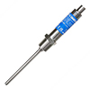
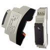
The RTD transmitter is usually powered by an unregulated power supply and is compatible with 2- or 3-wire RTDs. Upon receiving input, the transmitter sends output current that is directly proportional to the RTD sensor. The transmitter can be mounted on the surface or inside a protection head. Two copper wires are used to transmit the temperature signal and supply dc voltage to the transmitter.
Equipment needed for calibration of the RTD transmitter includes:
Equipment needed for calibration of the RTD transmitter includes:
- Precision Decade Resistance Box with ohm accuracy of ±0.02 and ohm resolution of 0.01 or
- Precision RTD simulator
- Precision DMM with mA accuracy of ±0.002 and mA resolution of 0.001
Connect the transmitter to the DC power supply and DMM monitor. Using copper wire, attach the transmitter to either an RTD calibrator or a Decade Resistance Box. On the transmitter, find the Z (zero) and S (span) potentiometers. Reference the manufacturer’s specifications to obtain the ohmic values for the Z (zero) and S (span) adjustments corresponding to the desired temperature range. If using an RTD simulator, select the appropriate Z (zero) and S (span) values. Set the Decade Resistance Box to the Z (zero) ohmic value that corresponds to the low end of the temperature range, and adjust the Z potentiometer to read 4.000 mA on the DMM monitor. Next, set the Decade Resistance Box to the S (span) ohmic value that corresponds to the high end of the temperature range, and adjust the S potentiometer to read 20.000 mA on the DMM monitor. Repeat the potentiometer adjustments until the values displayed are exactly 4.000 mA and 20.000 mA.
Conclusion
Temperature transmitters offer a great deal of flexibility in scaling the analog output signal in relation to the input. They isolate the signal, filter noise and amplify it for increased accuracy. RTD and thermocouple transmitters provide a full scale accuracy of ±0.1%. Temperature transmitters also provide stability by isolating signals from electromagnetic and radio frequency interference. Due to interaction between the S and Z potentiometers, repeat calibration is necessary.


 Omega's relationship with Rutgers sprouted with their goals in substituting manual processes with an IoT solution for hands-off data collection capabilities.
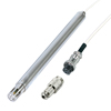
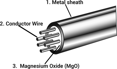 MI cables are used in high temperature or high pressure harsh environments for a good reason, here's why: